8.5 Boundary Condition (BC) Database
A boundary condition (BC) database is created using spreadsheet software such as Microsoft Excel. Two types of files are required:
- A database or list of BC events, including information on where to find the BC data.
- One or more files containing the boundary data (e.g. flow, level, rainfall data).
The database file must be .csv (comma delimited) formatted, or HEC-DSS (see Section 8.5.4). It must contain a row with the pre-defined keywords ‘Name’ and ‘Source’, as listed in Table 8.13. Other keywords control how data is extracted from the Source.
The BC data files can be in a variety of formats, as described for the ‘Source’ keyword in Table 8.13. Additional formats can be incorporated upon request. It is recommended that all .csv files originate from one spreadsheet with a worksheet dedicated to each .csv file. The Excel TUFLOW Tools.xlm macros can be used to export the worksheets to .csv format, see Section 17.2.5.
The active BC database is specified using the BC Database (.tcf file), BC Database (.ecf file) and/or BC Database (.tbc file) commands. Note, specifying BC Database in the .tcf file automatically applies to both 1D and 2D domains (i.e. there is no need to specify the command in the .ecf or .tbc files). The active database can be changed at any point by repeating the command in any of these files.
The maximum line length (i.e. number of characters including spaces and tabs) in a single line of a source file is 100,000 characters. If the keyword is not found in the “Name, Source” line, the default column is used to define the column of data for that keyword.
| Keyword | Description | Default Column |
|---|---|---|
| Name |
The name of a BC data location. The name must be the same name as used in the GIS 1d_bc, 2d_bc, 2d_sa, 2d_sa_rf or 2d_rf layers. It may contain spaces and other characters, though must not contain any commas. It is not case sensitive. The name of a group of boundaries can be used for RAFTS (.loc and .tot files) and WBNM (via the .ts1 file format) hydrographs. For example, if “N1|Local” is the boundary Name in a 1d_bc or 2d_bc layer, then the group is interpreted as the text to the right of the “|” symbol (i.e. Local), and the text to the left is the ID (i.e. N1) of the time-series data in the file containing the hydrographs. In this example, TUFLOW:
|
N/A |
| Source |
The file from which to extract the BC data. Acceptable formats are:
|
N/A |
| Column 1 or Time |
For .csv files, the name of the first column of data (usually time values in simulation hours) in the .csv Source File. Other examples besides Time are Flow for a HQ (stage-discharge) boundary, or Mean Water Level for each wave component in a 2D HS (sinusoidal wave) boundary. For all other types of Source entry (including FEWS .csv), leave this field blank. |
3 |
| Column 2 or Value or ID |
For .csv files, the name of the second column of data in the .csv Source File. For example, water levels in a HT boundary, flows for a QT boundary or water levels for a HQ boundary. For a Blank Source entry, the constant value to be applied. For example, to apply a mean water level to a HT boundary the source can be left blank and the water level entered in this column. For RAFTS-XP (.tot or .loc), WBNM _Meta.out and TUFLOW/ESTRY .ts1 files, the name of the hydrograph location to extract. For FEWS .csv and .xml boundaries the Location ID and Parameter ID need to be defined, separated by a vertical bar. The FEWS .csv file also supports event ensembles. For this an optional 3rd argument can be specified defining the ensemble ID. In the 1st boundary database entries below a FEWS .csv file is specified with the location ID “Location1” and the parameter ID “Q.sim.hist”. The 2nd boundary entry includes a boundary ensemble number 1. For external wind stress boundaries (.tesf), used to define the wind speed (m/s) Note: it is NOT possible to combine the Value and ID keywords in the column label, for example “Value or ID”. If they are combined, the default column number of 4 is used. |
4 |
| Add Col 1 or TimeAdd |
An amount to add to all Column 1 (normally time) values (e.g. a time shift) for the BC data event. If left blank or zero, there is no change to the time values. This field is ignored for Blank Source entries. |
5 |
| Mult Col 2 or ValueMult |
A multiplication factor to apply to the Column 2 values. If left blank or one (1), there is no change to the values. Note, Mult Col 2 is applied before Add Col 2 below. This field is ignored for Blank Source entries. |
6 |
| Add Col 2 or ValueAdd |
An amount to add to Column 2 values. If left blank or zero, there is no change to the values. Note, Add Col 2 is applied after Mult Col 2. For example, this could be used to add a base flow to a QT boundary or sea level rise allowance for a HT boundary. This field is ignored for Blank Source entries. |
7 |
| Column 3 |
For .csv files, the name of the third column of data when a third column of data is required. For example, the phase difference for each wave component in a 2D HS (sinusoidal wave) boundary. For external wind stress boundaries (.tesf), used to define the wind direction (degrees relative to East, ie. East = 0º, North = 90º, etc.). For all other types of Source entries, leave this field blank. |
8 |
| Column 4 |
For .csv files, the name of the fourth column of data when a fourth column of data is required. For example, the period for each wave component in a 2D HS (sinusoidal wave) boundary. For all other types of Source entries, leave this field blank. |
9 |
8.5.1 BC Database Example
Figure 8.4 shows a simple example of a BC database setup in a worksheet that is exported as a .csv file for use by TUFLOW.
TUFLOW searches through the file until a row is found with the two keywords Name and Source. Name and Source do not have to be located in Columns 1 and 2 (although this is recommended).
Table 8.13 describes the purpose of each keyword and the default column where applicable. At present a range of formats are accepted, and other formats can be incorporated upon request.
The example above is interpreted as follows:
- A boundary condition data location named “Level” is found in a boundary condition GIS file (eg. 2d_bc, 2d_sa, 2d_rf etc.). The boundary condition time-series data associated with it are found in the file heads.csv. Within the csv file, the time values are located under a column called “Time” and the BC values are located under a column “Lake Level”.
- As an alternative to “Level” above, a boundary condition data location “Level (alternative)” is set a constant value of 2.
- A boundary condition data location named “River Inflow” is found in a boundary condition GIS file. The time-series data associated with it is available in flows.csv. Within flows.csv, time details are found in the column titled “Time 1”. Boundary condition values are found in the column titled “River Flow”. Similarly, “Creek Inflow” and “Base Flow” are also located in flows.csv.
- A boundary condition data location named “RAFTS Inflow” extracts the hydrograph from a RAFTS-XP .tot file named “rafts.tot” for RAFTS node “IN”.
The heads.csv and flows.csv files are created by saving the worksheets “heads.csv” and “flows.csv” as .csv files (see Figure 8.5 and Figure 8.6).
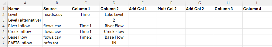
Figure 8.4: Simple BC Database Example (bc_dbase.csv)
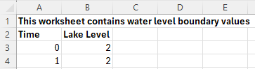
Figure 8.5: Example BC Database Source Files (heads.csv)
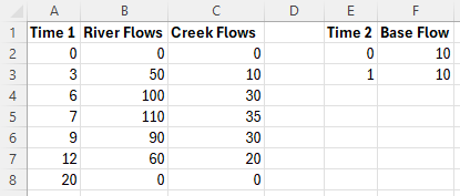
Figure 8.6: Example BC Database Source Files (flows.csv)
8.5.2 TUFLOW Boundary Generators
The development of boundary conditions is usually model specific, although there are some common regional approaches to flow and rainfall generation. To assist with this, a number of boundary generator tools have been created within QGIS which allow the modeller to semi-automate the production of the BC Database, boundary data files for different events, patterns and storm duration and also an associated TUFLOW Event File. Currently, these exists for 3 regional hydrological approaches. For a description of each, the reader is referred to the relevant Wiki page:
- Australian Rainfall and Runoff 2019 Tool (ARR to TUFLOW tool): The ARR to TUFLOW tool interacts with the Australian Bureau of Meteorology website, in conjunction with ARR input parameters, to generate rainfall hyetographs together with optional soil loss files depending on the method (tsoilf or material.csv).
- UK Revitalised Flood Estimation Handbook 2 (ReFH2 to TUFLOW tool): This allows both flow hydrographs and rainfall hyetographs to be developed for a TUFLOW simulation for a range of events and storm durations based on imported FEH Catchment or point descriptors.
- Auckland Region SCS to TUFLOW tool. This tool allows flow hydrographs to be developed for the Auckland, New Zealand region using the U.S. Soil Conservation Service (SCS) (now known as the Natural Resources Conservation Service, part of the U.S. Department of Agriculture) rainfall-runoff model. The implemented approach complies with Auckland City Council’s TP108 policy.
Please let support@tuflow.com know if you have suggestions for a boundary conditions generators
8.5.3 Delft FEWS Boundaries
Boundary timeseries in the Delft FEWS boundary format are supported, as shown in Table 8.13.
Delft FEWS .csv and .xml files are TUFLOW compatible. In both cases the keyword “FEWS” is required in the ‘Source’ field of the BC Database followed by a vertical bar “|” and then the Delft FEWS filename (for example FEWS | <sourcefile.csv>). Following ‘Source’ in the BC Database:
- ‘Column 1’ is not required. This is due to TUFLOW sourcing time information directly from the Delft FEWS file.
- ‘Column 2’ is needed to define the Location ID, Parameter ID, and when using the .csv format, the Ensemble ID. Each parameter is separated by a vertical bar. For example:
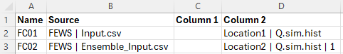
Note, ensemble ID information is only possible using the Delft FEWS .csv format. It is not possible using Delft FEWS xml format.
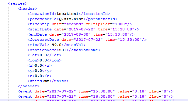
The header section for an input .xml is shown below. Any data in the timeseries with the value equal to that defined by the <missVal> in the header are ignored. Additional header tags are ignored by TUFLOW.
The FEWS Input File command can be used to set the duration of the TUFLOW simulation and the NetCDF Output Start Date based on information within the FEWS boundary file. FEWS Input File can refer to either a FEWS .csv or FEWS .xml file. Using this command, the duration and End Time value of the TUFLOW simulation is determined from the Delft FEWS input file. If using this approach, no End Time command should be included in the .tcf file. The start date defined in the FEWS input file is used to set the NetCDF output start date (e.g. NetCDF Output Start Date).
8.5.4 HEC-DSS Boundaries
The 2023-03 release introduced support for time-series data from HEC-DSS files within a boundary condition database. HEC-DSS is a database system for time series, curve, gridded data and more, developed by the U.S. Army Corps of Engineers Hydrologic Engineering Center (HEC). See their website at https://www.hec.usace.army.mil/software/hec-dss/ for more information. It is used by the HEC developed models for data input and output. Rather than convert HEC-DSS time-series curves for use in TUFLOW, this data can be accessed directly. HEC-DSS files organise data into paths with six parts (Part A – Part F) that resemble how files are organised on disk. Figure 8.7 shows an example DSS file with a single path, with the curve plotted below.
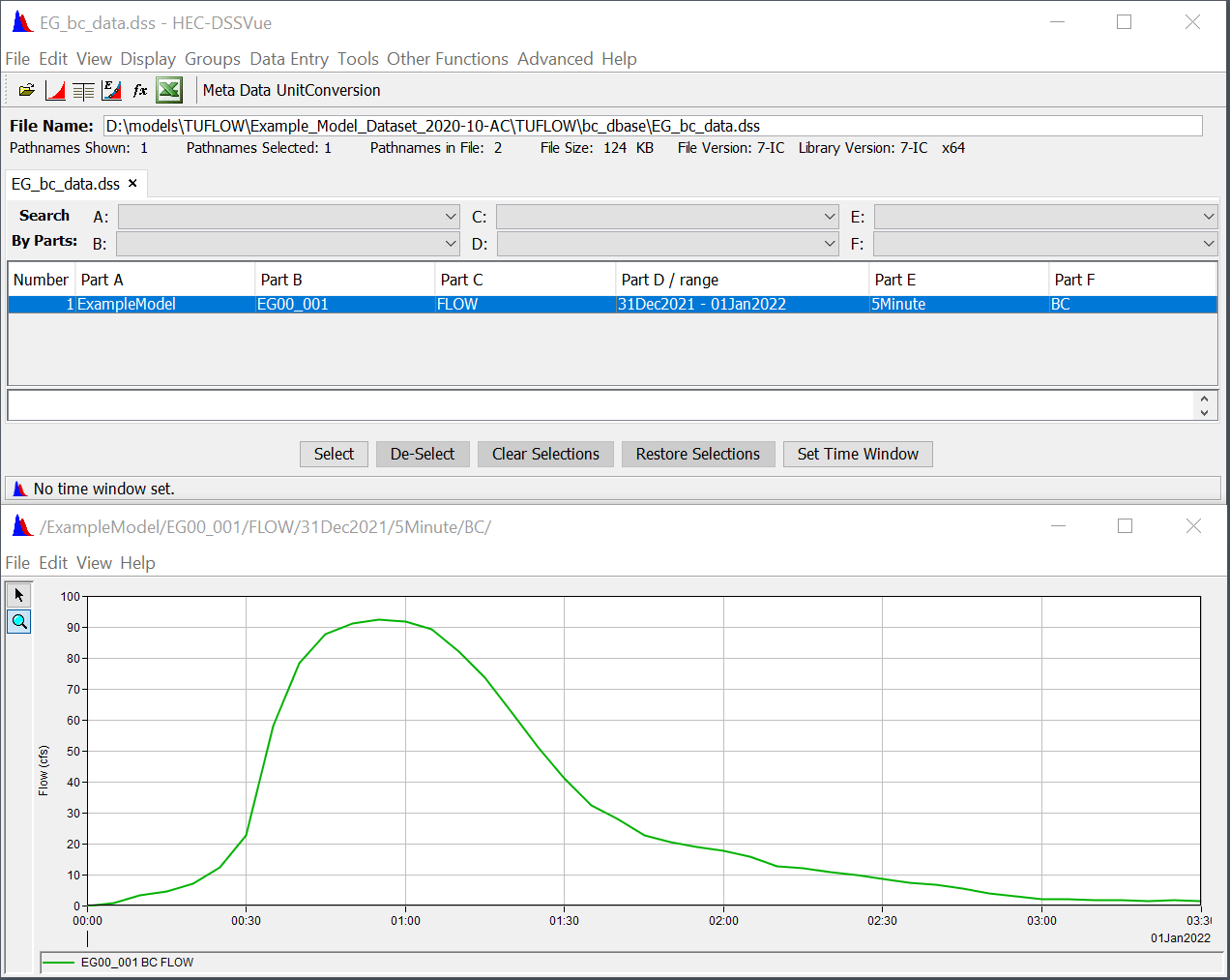
Figure 8.7: Example DSS File
To use a HEC-DSS time-series curve within a TUFLOW boundary condition database:
- Provide the filename in the “Source” column.
- Leave “Column 1”, which is used for time, blank (DSS files store the time with the curve values).
- Identify the pathname in “Column 2.” Event placeholders such as event can be used as part of the pathname. Wildcards (*) can be used for parts of the path, however, ensure the wildcards will not select more than one path within the file.
- The “Add” and “Mult” columns can be used to offset or scale the time-series values, the same as non-DSS time-series curves.
Figure 8.8 shows how the time-series curve above could be included in a boundary condition database. A wildcard is used for Part D of the pathname (date range). Note that the pathname must start with a forward slash (/).
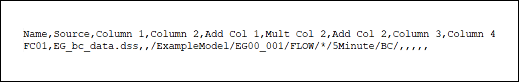
Figure 8.8: Time-series Curve Example
By default, TUFLOW uses the first point in the time-series curve as TUFLOW time-zero. This can be changed using the new command “
Note: Non-time series data such as gridded data from a HEC-DSS file is not supported.