10.5 Flood Modeller to TUFLOW Linking
TUFLOW 2D domains can be dynamically linked to Flood Modeller (previously known as ISIS). Flood Modeller can also link to TUFLOW 1D (previously known as ISIS-TUFLOW-PIPE or ISIS-ESTRY).
Unlike TUFLOW 1D or SWMM, Flood Modeller is not included in the TUFLOW executable download. It must be installed and configured to support the linking to TUFLOW. The TUFLOW Link must be purchased from Jacobs and an appropriate software version used. It is recommended that TUFLOW 2020-10-AD or later is used in conjunction with Flood Modeller Version 5 or later. Figure 10.15 provides the compatibility between Flood Modeller and TUFLOW for versions prior to Flood Modeller 6 and TUFLOW 2020-10-AE. Post these releases, all TUFLOW Classic and TUFLOW HPC (including Quadtree) functionality is supported and compatible with Flood Modeller. Versions prior to Flood Modeller 4.5 will support TUFLOW Classic only. Regardless of the TUFLOW 2D solver (i.e. Classic or HPC), the linking mechanism is the same.
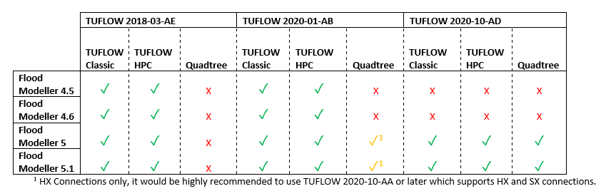
Figure 10.15: Compatibility of Recent Flood Modeller and TUFLOW versions
10.5.1 Flood Modeller 1D to TUFLOW 2D Linking
To link Flood Modeller’s 1D scheme to TUFLOW 2D, a TUFLOW 1d_x1d GIS layer defining the locations of the Flood Modeller 1D nodes is required. The 1d_x1d layer can either be created by the user or by the Flood Modeller interface.
For linking 1D Flood Modeller to TUFLOW 2D, the TUFLOW 1d_x1d layer requires only one attribute, namely a string 12 characters long that contains the unique IDs of the Flood Modeller 1D nodes/sections. Any other attributes are presently ignored. Creation of this layer manually is possible through exporting a text or csv file containing the Node ID and XY coordinates of the nodes, provided the Flood Modeller co-ordinates are in the same projection as the TUFLOW model. Note, the IDs are case sensitive (because Flood Modeller IDs are case sensitive).
In the .tcf file, use either the Read GIS X1D Nodes or Read GIS X1D Network command to read the 1d_x1d layer, as shown in the example below:
The digitising of channels (lines) within a 1d_x1d GIS layer is optional and is only necessary if the model uses 1D Water Level Lines to display map outputs in the 1D domain (refer to Section 11.2.4 for further details). If GIS layer(s) are provided including channels, they are also read into the .tcf file using the command Read GIS X1D Network, and should be used with Read GIS X1D WLL.
The example below shows the use of these commands (with the nodes and channels in separate files):
Note, legacy models may include reference to ISIS in the above commands. For example, “X1D” in Read GIS X1D Network can be substituted with “ISIS” (i.e. Read GIS ISIS Network).
Connections (CN) in the 2d_bc layer are snapped to the nodes in the 1d_x1d layer in the same manner as a TUFLOW 1D 1d_nwk layer.
The following restrictions apply when connecting Flood Modeller nodes to TUFLOW 2D:
- HX lines should only be connected to Flood Modeller RIVER units. Flood Modeller INTERPOLATE and REPLICATE units are also permitted. This requires that the Flood Modeller unit between consecutive connections along a HX line is always a RIVER unit. If this is not the case, an “ERROR 2043 - 2D HX cell has been assigned to a non-RIVER unit” occurs. Where a non-RIVER unit occurs (e.g. at a structure), the HX line needs to be broken.
- Special Flood Modeller units may be required for some HX and SX connections (refer to the Flood Modeller documentation).
It is not necessary for all Flood Modeller RIVER units between the upstream and downstream ends of the HX line to be connected. Nodes/Sections may be intentionally or accidentally omitted as with TUFLOW 1D nodes. Please note that this is not recommended because by missing or omitting nodes the 1D water level water surface gradient that is applied along the HX lines will not be correctly represented.
TUFLOW checks whether the ZC elevation of a HX cell lies above the bed of the 1D nodes and that the ZC elevation of a SX cell lies below the 1D node bed, and if not, an error occurs (see Section 10.2.1 and Section 10.2.2).
Use the _x1d_nodes_check file to cross-check the external 1D nodes/sections that were read by TUFLOW, and the associated information passed from the 1D scheme. Also use the _1d_to_2d_check file to cross-check the correct HX and SX cells are connected to the correct channels (units). The HX cells in the _1d_to_2d_check layer can be colour coded using the “Primary_no” attribute to identify the external 1D channel (unit) that the flow in/out across the HX cells is associated with. For Flood Modeller, by default HX cells are assigned to the upstream end of a river unit as a lateral flow as per Flood Modeller conventions.
Note, the start and end simulation times and the timestep are controlled by Flood Modellers GUI input fields, and any Start Time, End Time and Timestep commands are ignored in the .tcf file. It is best practice to remove (or comment out) these commands. Within the Flood Modeller GUI, the Flood Modeller 1D timestep can differ from the TUFLOW timestep. It is recommended that the Flood Modeller timestep be set as an integer divisor of the TUFLOW timestep.
No TUFLOW 1D .ecf file is required, and the TUFLOW 1D ESTRY Control File command should not be specified unless there are also TUFLOW 1D domain(s) in addition to the external scheme 1D domain(s). Flood Modeller nodes can be directly linked to TUFLOW 1D nodes allowing models to have a combination of Flood Modeller 1D and TUFLOW 1D (ESTRY) - refer to Section 10.5.2. An example model demonstrating both ‘SX’ and ‘HX’ type links between Flood Modeller and TUFLOW is available here.
Note that Flood Modeller HX links may benefit from assigning a Form Loss Coefficient (typically 0.1 to 0.5 in value) to HX lines using the 2d_bc “a” attribute. For HX lines running along the riverbanks, especially those with high overtopping velocities, improved stability and representation of the energy losses associated with the water peeling off from the river to the floodplain or vice versa can be achieved.
For model review purposes, the .tcf command Write X1D Check Files writes out check_x1D_H_to_2D.csv and check_2D_Q_to_x1D.csv files. These contain the water levels and flows sent to the 2D to/from Flood Modeller.
Example models demonstrating TUFLOW / Flood Modeller linking are available from the TUFLOW Gitlab User Group. Detailed documentation for the example models is available from the TUFLOW Wiki 1D Flood Modeller Connectivity. A TUFLOW / Flood Modeller linked model is provided in TUFLOW / Flood Modeller Tutorial Module 1.
10.5.2 Flood Modeller 1D to TUFLOW 1D (ESTRY) Linking
TUFLOW 1D (ESTRY) domains can be dynamically linked with Flood Modeller. The most common reason this is carried out is to utilise TUFLOW 1D’s powerful pipe network features (see Section 5.10).
Flood Modeller and TUFLOW 1D (ESTRY) nodes will be considered linked if:
- A TUFLOW 1D node in a 1d_nwk layer, and a Flood Modeller node in a Read GIS X1D Nodes or Read GIS X1D Network layer are snapped.
- Note, legacy models may include reference to ISIS in the command. For example, “X1D” in Read GIS X1D Nodes can be substituted with “ISIS” (i.e. Read GIS ISIS Nodes).
- Note, legacy models may include reference to ISIS in the command. For example, “X1D” in Read GIS X1D Nodes can be substituted with “ISIS” (i.e. Read GIS ISIS Nodes).
- The TUFLOW 1D node connection method is defined using the TUFLOW 1D 1d_nwk Conn_1D_2D attribute. If the Conn_1D_2D field is blank, a “X1DH” type is assumed - this is the default approach. Alternatively, a value of “X1DH” or “X1DQ” can be manually specified.
- A “X1DH” link means a Flood Modeller 1D water level is applied at the TUFLOW 1D node (i.e. Flood Modeller sends TUFLOW 1D a water level and TUFLOW 1D sends back a +/- flow to Flood Modeller).
- A “X1DQ” link means a Flood Modeller inflow/outflow is being applied at the TUFLOW 1D node (i.e. Flood Modeller sends TUFLOW 1D a +/- flow and TUFLOW 1D sends back a water level).
- If the end of the TUFLOW 1D channel and the snapped Flood Modeller / TUFLOW 1D nodes are not in the same location a TUFLOW 1D 1d_nwk connector “X” channel type can be used to connect the end of the linked TUFLOW 1D channel to the TUFLOW 1D node snapped to the Flood Modeller node.
- Note that the upstream and downstream inverts for the TUFLOW 1D node linked to Flood Modeller should be set to -99999 unless the node is also being used to set the inverts of channels snapped to it.
- As a general rule, a TUFLOW 1D X1DH (the default) would be used for most Flood Modeller TUFLOW 1D links. An X1DQ might be more appropriate where a Flood Modeller model stops and flows into a TUFLOW 1D model.
Generally, a TUFLOW 1D timestep will be smaller than the Flood Modeller timestep. In these cases, the total volume is accumulated over all TUFLOW 1D timesteps within a Flood Modeller timestep, and applied to the Flood Modeller model as a discharge by dividing the volume by the Flood Modeller timestep.
When running a TUFLOW 1D Flood Modeller linked model, the mass balance output _MB1D.csv file includes four new columns (which are not present if the 1D-1D linking is not used):
- X1DH V In: The volume of water in via a X1DH link.
- X1DH V Out: The volume of water out via a X1DH link.
- X1DQ V In: The volume of water in via a X1DQ link.
- X1DQ V Out: The volume of water out via a X1DQ link.
Also, for model review purposes, the type or existence of a connection can be checked following a simulation by viewing the Conn_1D_2D attribute in the _nwk_N_check layer. The _messages GIS layer also contains CHECK 1393 messages at each TUFLOW 1D node linked to a Flood Modeller node.
Example models demonstrating TUFLOW Flood Modeller linking are available from the TUFLOW Gitlab User Group. Detailed documentation for the example models is available from the TUFLOW Wiki 1D Flood Modeller Connectivity. A TUFLOW 1D Flood Modeller linked model is also provided in TUFLOW / Flood Modeller Tutorial Module 2.