10.7 Multiple 2D Domains
The Multiple 2D Domain Module license provides access to TUFLOW HPC’s Quadtree and TUFLOW Classic’s Multiple 2D Domain (M2D) features. Both of these features allow the 2D cell resolution (cell sizes) to vary across the model. However, they are very different in their hydraulic solution and construct as described below.
10.7.1 Classic’s M2D Feature versus HPC Quadtree
- TUFLOW HPC only supports one 2D domain, however, the 2D cell size can be varied within the domain using the quadtree grid feature. In contrast, TUFLOW Classic’s M2D feature allows different 2D domains of different cell size/orientation to be linked together via hidden 1D nodes and HX lines.
- For a HPC quadtree grid, the numerical solution remains a full 2D solution without loss of accuracy, undesirable numerical artefacts or wave reflections when transitioning from one cell size to another. For Classic’s M2D feature, there is a loss of accuracy, particularly where the flow is complex/circulating and the assumptions associated with momentum and the linear water level profile associated with HX lines are influential.
- TUFLOW HPC Quadtree grids are set up by the modeller using a largely automated approach. Definition of 2D cell resolution regions is all that’s required. By comparison, TUFLOW Classic M2D requires manual definition of each 2D domain and the linkage between domains using 2D-2D links.
Please contact sales@tuflow.com if you wish to use these features, but do not have the M2D/Quadtree Module enabled on your licence.
Due to the workflow efficient nature of its implementation, superior stability, numerical accuracy and preservation of inertia, TUFLOW HPC Quadtree has superseded TUFLOW Classic’s Multiple 2D Domain (M2D) feature as the recommended approach for models that require varied 2D cell sizes within a single model.
For a complete description of the 2D TUFLOW HPC Quadtree solution and associated commands, please refer to Section 7.3.1.
An example TUFLOW HPC Quadtree model is available in TUFLOW Tutorial Module 7. A video demonstration the implementation of this multiple 2D Domain feature is also available in the TUFLOW Library.
10.7.2 TUFLOW Classic’s Multiple 2D Domains
When using TUFLOW Classic with the M2D feature, any number of 2D domains of different cell size and orientation can be combined to form one model. The 2D domains can be linked via 1D domains or directly to each other. For example, a 1D domain of a river system may have several 2D domains embedded to represent several towns where a more detailed analysis is required. Alternatively, direct 2D to 2D linking can be achieved by using the 2d_bc 2D link type (see Section 8.4). Examples of these model configurations are shown in Figure 10.16 and Figure 10.17.
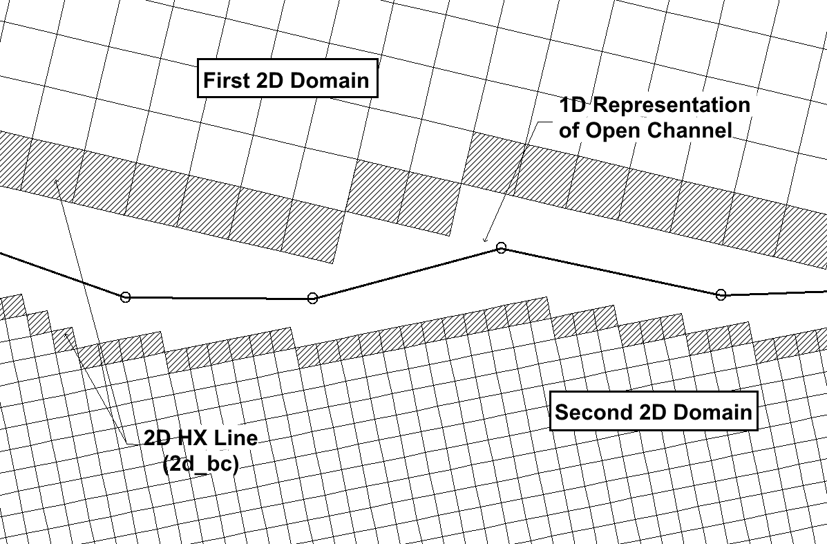
Figure 10.16: Schematic of a Multiple Domain Model linked via a 1D Domain
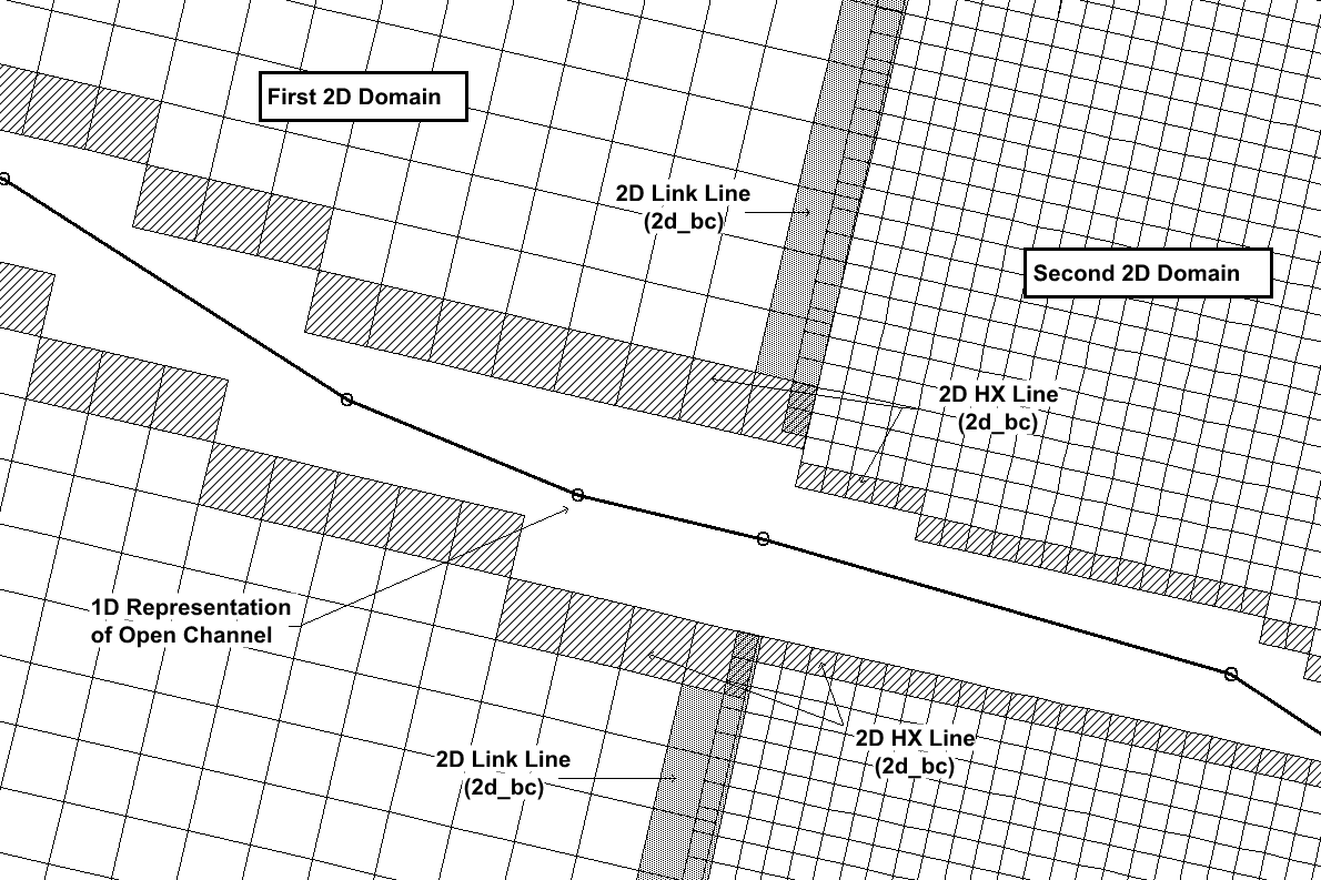
Figure 10.17: Schematic of a Multiple 2D Domain Model using the 2d_bc “2D” Link
To specify more than one 2D domain use Start 2D Domain and End 2D Domain in the .tcf file to start and end blocks of commands applicable for each 2D domain. The ESTRY Control File and BC Database commands are independent of the 2D domain block. As such they are typically not included within the 2D domain block.
The mandatory .tcf commands that occur within a 2D domain block are:
|
Geometry Control File BC Control File |
Timestep |
|---|
Optional commands that can be used are:
|
Cell Wet/Dry Depth Instability Water Level Read GIS FC Read GIS GLO |
Read GIS IWL Read RowCol IWL Read GIS LP Read GIS PO |
|---|
Note that specifying one of the above commands outside a Start/End 2D Domain block does not apply that command to all 2D domains. For example, specifying Cell Wet/Dry Depth outside a lock will not set the Cell Wet/Dry Depth value to all 2D domains, and causes ERROR 2107 to occur.
An example of using 2D domain blocks is given below:
Multiple 2D domain models use the 2d_bc “2D” link type (see Table 8.5 and Table 8.6) as the boundary cells that transfer flow between the neighbouring domains. The link type creates hidden 1D nodes at each vertex along the 2D link line and also at a regular interval, as defined by the “d” attribute (see Table 8.6). The hidden 1D nodes act as storage that convey the water from one 2D domain to the other.
The water levels along the 2d_bc 2D link line are linearly interpolated using the water levels in the hidden 1D nodes. If the water level profile in reality is not close to linear between vertices, strange flow patterns may occur which can lead to model instability or unrealistic results. As such, appropriate resolution of the hidden 1D nodes is an important feature of multiple 2D domain models.
The .tcf command Reveal 1D Nodes can be used to view the hidden 1D nodes. The hidden nodes will be written to the nwk_N check layer, as shown in Figure 10.18 . For multiple domain models using the 2d_bc “2D” link, note that this GIS layer must be read into the .tbc files of both 2D domains. The 2D link can then be checked by viewing the _2d_to_2d_check layer which displays the 2D cells used to link the two domains together. These features, and their check files are shown in Figure 10.18.
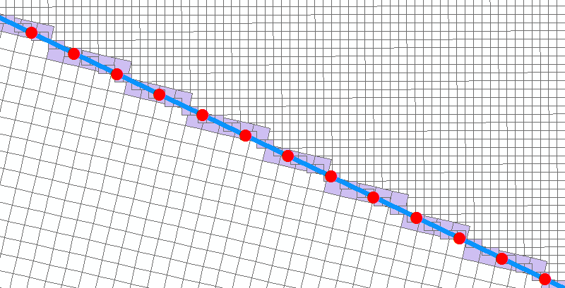
Figure 10.18: Multiple 2D Domain Model “2D” Link Check Files
The following guidance is recommended when defining the location and orientation of the 2d_bc “2D” link.
- 2D link lines will be most stable if digitised perpendicular to the dominant flow direction in high conveyance locations (e.g. rivers and creeks).
- Orientation of the 2D link lines is less critical in low conveyance regions, such as floodplain storage areas (i.e. perpendicular orientation is not a necessity). High resolution definition of the hidden 1D nodes may be required. If used, the automated hidden 1D nodes distance attribute “d” should not be set finer than three times the larger cell size.
If the extents of the 2D domains overlap, it will be necessary to deactivate the overlapping cells in the other domain. Using the example above, the active area for the ‘West Domain’ will need to be deactivated in the .tgc file of the ‘East Domain’ and vice versa. The Read GIS Code Invert command is useful for this process as it allows for the same GIS layer to be used to active/deactivate cells.
A unique model Timestep is recommended for each 2D domain. The timestep should be defined so that it conforms to the Courant stability criteria for each domain, as discussed in Section 3.4.3. The timesteps of all 2D and 1D domains should be an integer multiple of one another.
A TUFLOW Classic Multiple 2D Domain model is available in TUFLOW Tutorial Module 9 Archive.
