5.1 Schematisation
1D domains are made up of a network of channels and nodes, shown in Figure 5.1, where:
- Channels represent the conveyance of the flow paths. The channels are flow and velocity computation points in the 1D model. Channels could refer to 1D open channels, where the flow and velocity are calculated based on the 1D unsteady St Venant fluid flow equations (see Section 5.5); and 1D structures (such as pipes, culverts, bridges, weirs, gates, etc.), where the flow and velocity are computed based on empirical flow equations (see Section 5.7).
- Nodes represent the junctions of channels and the storage capacity of the network (see Section 5.12). These are water level computation points in the 1D solution.
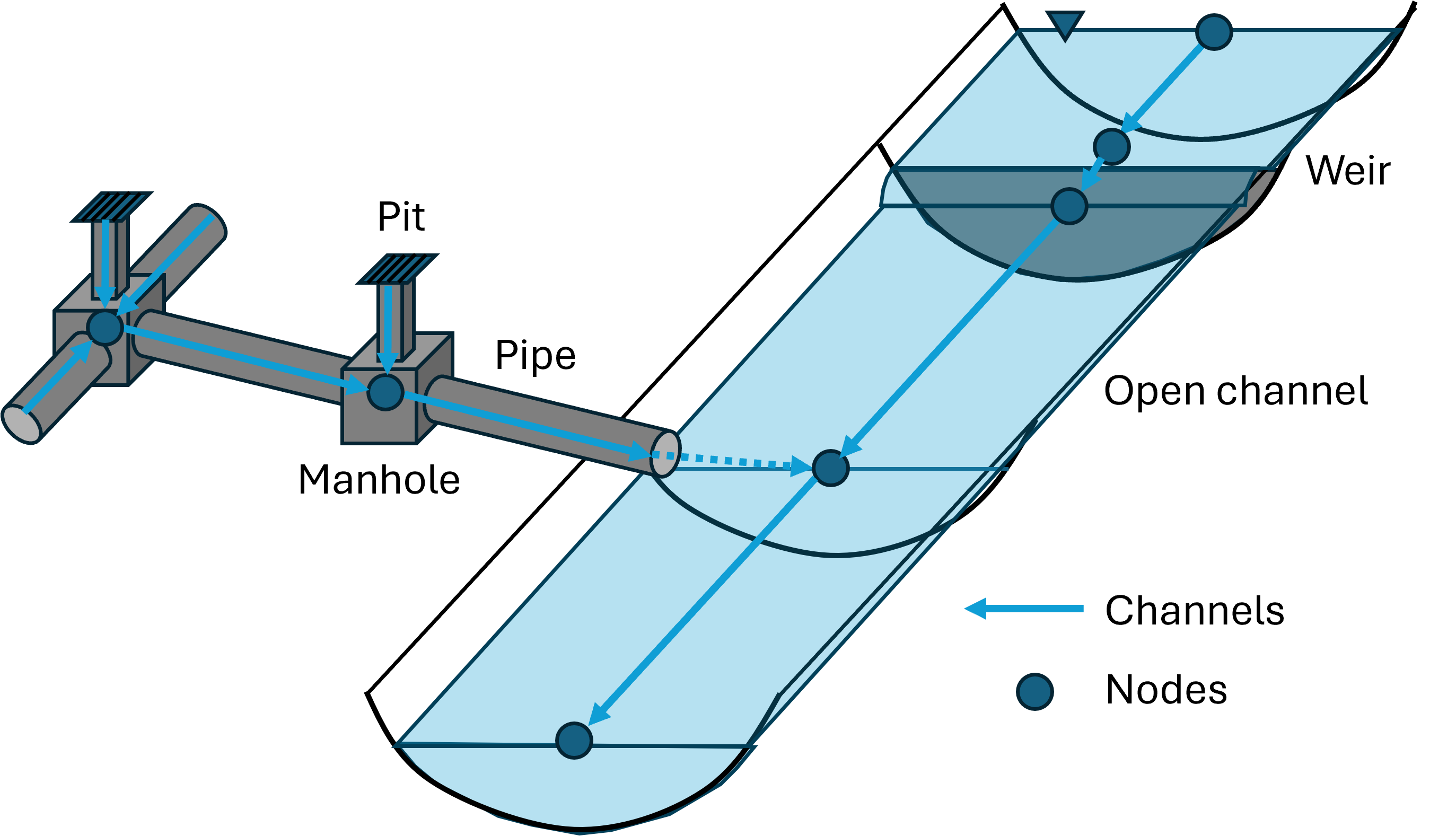
Figure 5.1: 1D Channels, Structures and Nodes
Both channels and nodes are created using one or more GIS layers (primarily using the generic 1d_nwk layer, but other speciality layers can be used such as 1d_pit for inlets and 1d_mh for manholes). There are no constraints on the complexity of the network with any number of channels being able to connect to a single node. Each channel is connected to two nodes; one at the channel’s upstream end the other at its downstream end. The digitising of nodes is optional. In most models these are automatically created.
Multiple GIS layers can be specified. Subsequent layers are used to modify the network at individual objects. For example, if a culvert is to be upgraded in size, rather than making a copy of the whole 1d_nwk layer, select the culvert channel, save the culvert as another 1d_nwk layer and modify the channel to represent the upgraded culvert. Use Read GIS Network twice to first read in the base 1d_nwk layer, then the 1d_nwk layer with the single channel representing the upgraded culvert. Provided the channel has the same ID and is snapped to the same nodes, it will override the original culvert channel. Using this approach minimises data duplication and, if executed logically and in a well-documented manner, is a very effective approach to modelling.
The attributes required in the 1d_nwk layer depend on the channel or node type. Table 5.1 and Table 5.30 present the available channel and node types respectively. Section 5.3 presents links to all tables of attributes within the 1d_nwk layer for all channel and node types.
If using more than 100,000 channels see Maximum 1D Channels.