10.4 SWMM to TUFLOW Linking
New in the 2023-03-AD release, TUFLOW’s 1D linking and solver options have been expanded to support the EPA Storm Water Management Model (SWMM), see Chapter 6. The SWMM engine (version 5) has been integrated into the TUFLOW executable as a 2D and 1D dynamically linked 1D solver. SWMM version 5 input (.inp) files can be directly input to TUFLOW.
In TUFLOW-SWMM there are three categories of connections between SWMM 1D and TUFLOW:
- Direct Connections: These apply to inlets/outlets associate with culverts passing through an embankment (modelled in 2D), or also open outlets from a pipe network.
- Storm-Drain Inlets: These apply to surface pits/inlets for capturing overland flow into a pipe network. Geometry information associated with the storm-drain inlet is used to determine the discharge that should flow from the 2D domain into the 1D SWMM pipe network.
- SWMM 1D connection to TUFLOW 1D (ESTRY) that allows 1D domains to be a combination of ESTRY and SWMM.
10.4.1 1D Culvert Connections to 2D Domains
This type of connection is used for cross-drainage such as culverts through an embankment. Due to limitations within SWMM, HX connections are used at the Nodes–Storage object (upstream side) and SX connections are applied at the Nodes–Outfalls object (downstream). This configuration is presented in Figure 10.11.
Where a Nodes–Storage point is connected to the 2D domain using an inlet or HX connection, TUFLOW will compute the discharge that should be transferred between the 1D and 2D domain. If the water level in the 2D domain is higher than the 1D (potentially ponded) water level, then flow will be transferred from the 2D domain to the 1D. The discharge rate will depend on the difference in water levels.
A TUFLOW-SWMM culvert model is provided in the TUFLOW-SWMM Tutorial Module 1.
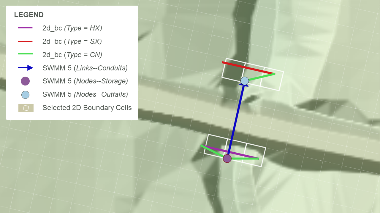
Figure 10.11: SWMM 1D Connection: Culvert
10.4.2 1D Pipe Network Connections to 2D Domains
SX type linking described in Section 10.2.2.1 is recommended for pipe network storm-drain inlets. For a TUFLOW-SWMM model, storm-drain inlets can be defined in one of two ways, either:
- Fully defined in a SWMM input (.inp) file format: In this form, all table items listed below (Streets, Conduits, Inlets, and Inlet Usage) are required. In addition, a “2d_bc” layer is required to provide the connectivity between the 1D inlets and the 2D domain.
- Streets: SWMM uses the street cross-section information in this table to help compute storm drain inlet discharges, particularly for on-grade inlets.
- Conduits (Streets): The conduits table is used to define streets for overland runoff and the slope is used in the storm drain inlet discharges. This table is not used directly when running a TUFLOW-SWMM model because the overland flows are calculated within TUFLOW.
- Inlets: This table defines inlet configurations that describe how to determine inlet discharges. Inlets can be defined based on type and shape such as grates, curbs, and combination, or through curves that describe the relationship between depth and inlet discharge or approach flow and inlet discharge. The inlets table defines these parameters. The same inlet configuration can be used in multiple pit locations within the model.
- Inlet Usage: This table identifies the placement of inlets including the street conduit, inlet (configuration), the node receiving the flow, and local parameters including blockage, size of local gutter depressions, and specification of on-grade, on-sag placement, or automatic placement.
- Streets: SWMM uses the street cross-section information in this table to help compute storm drain inlet discharges, particularly for on-grade inlets.
- Defined using a SWMM input (.inp) file with a “swmm_inlet_usage” GIS layer: In this form TUFLOW creates a GIS layer to assist in the 1D-2D specification. Due to reduced data requirements and model build workflow efficiency the combined SWMM input (.inp) file / “swmm_inlet_usage” GIS layer format is the recommended approach. Using this format:
- Table 10.1 lists the attributes associated with the swmm_inlet_usage GIS layer.
- Automatic inlet connections between the 1D network and 2D domain can be implemented via the “Conn1D_2D” attribute field (instead of manual specification of SX connection cells within a “2d_bc” GIS layer).
- SWMM 5 “Inlet Usage” tables are not used, and Conduits (Streets) are not required. However, Streets and Inlet tables must be defined in the SWMM input (.inp) file.
- 2d_bc SX lines may be used to manually define connections associated with on-grade inlets. This gives the user complete control over the 2D cells selected for the on-grade flow calculations.
- The conventional 1D-2D link approach using 2d_bc CN lines and SX lines can be used (instead of the automated methods) should greater control be required over the selected 2D cells for the 1D-2D on-grade inlet connections.
- The conventional 1D-2D link approach using 2d_bc HX lines and SX points, lines or regions is required to connect 1D channel ends where “direct” connection to the 2D is desired.
- Table 10.1 lists the attributes associated with the swmm_inlet_usage GIS layer.
An example model configuration is shown in Figure 10.12, and example TUFLOW-SWMM pipe network models are also provided in TUFLOW-SWMM Tutorial Modules 2, 3 and 4.
Whether inlet usage details are defined in SWMM or in a separate GIS layer, the inlet discharges are computed within TUFLOW using EPA SWMM 5.2 code before being passed to the SWMM engine for the 1D solution computations. This approach has been selected to leverage the 2D domain hydraulic calculations.
If the pressure head in the 1D domain exceeds the 2D water level, the 1D domain will overflow (surcharge) into the 2D domain. The approach used to compute the surcharge discharge depends on the inlet setup and whether or not the SWMM node ponds.
- If the node allows ponding (ponding > 0) (recommended configuration):
- The surcharge discharge is based on the depth vs flow curve for custom inlets or from the orifice equation for other inlet types, plus any additional discharge from the use of the Maximum Inlet Ponded Depth command.
- The coefficient used for inlet surcharging can be specified with the Inlet Surcharge Orifice Coefficient command.
- The discharge for custom curves is applied directly in reverse. For example, a 1D water level 0.3 feet above the 2D water level will produce the equal, though opposite, discharge as a 2D water level 0.3 feet above the 1D water level (or ground elevation).
- The surcharge discharge is based on the depth vs flow curve for custom inlets or from the orifice equation for other inlet types, plus any additional discharge from the use of the Maximum Inlet Ponded Depth command.
- If the node does not allow ponding (ponding = 0):
- Any volume that exceeds the maximum nodal water level (YMax) plus any surcharge depth (YSur) is reported as flooding by SWMM, which no longer tracks it. The water is passed directly from the SWMM engine to the TUFLOW 2D cells. Although possible, this approach is not recommended because it prevents the 1D network from utilising the full pressure head in its flow calculations.

Figure 10.12: SWMM 1D Connection: Pipe Network
| No. | Default GIS Attribute Name | Description | Type |
|---|---|---|---|
| 1 | Inlet | The name of the inlet defined in the SWMM inp file “INLETS” section | Char (100) |
| 2 | StreetXSEC | The name of the street cross-section that must be included in the SWMM SWMM inp file “Streets” section. | Char (100) |
| 3 | Elevation | The elevation of the inlet. If a value of –99999 is entered, the elevation will be based on the 2D cell’s elevation. | Float |
| 4 | SlopePct_Long | The longitudinal slope of the street near the inlet. | Float |
| 5 | Number | The number of inlets in series at the location (generally 1). | Integer |
| 6 | CloggedPct | The percentage that the inlet is blocked (defaults to 0.0). | Float |
| 7 | Qmax | The maximum discharge through the inlet (default is 0 which does not enforce a maximum). | Float |
| 8 | aLocal | The depth of a local depression at the inlet (default 0.0). | Float |
| 9 | wLocal | The width of a local depression at the inlet (default 0.0). | Float |
| 10 | Placement | Specifies whether the inlet should be treated as a sag or on-grade. Options are ON_GRADE, ON_SAG, or AUTOMATIC. AUTOMATIC (the default) will switch between ON_GRADE and ON_SAG depending upon the flow conditions at the inlet. | Char(10) |
| 11 | Conn1D_2D |
Used to specify a “SX” connection and any additional flags such as “SXZ” or “SXG” that automatically creates a 2D SX cell and connection at the 2D cell within which the SWMM node occurs. This negates the need to create SX objects in a 2d_bc layer. Flags:
|
Char (10) |
| 12 | Conn_Width |
If “SX” is specified for Conn1D_2D, this field controls the number of 2D cells connected as follows. Note this approach is slightly different than is used by TUFLOW-ESTRY models.
|
Float |
10.4.3 Groundwater Connections to 2D Domains
A SWMM 1D model can connect to TUFLOW groundwater layers as described in Section 10.2.2.2. For groundwater to 1D connections (1D draining groundwater), an inlet is required to represent the connectivity (see Table 8.6), as shown in Figure 10.13. This inlet is typically a generic inlet (see Table L.17) which uses a depth vs discharge relationship to define the flow. If water is being pumped into the groundwater system (e.g. an intentional recharge situation), an inlet is not required.
Guidance for generating depth vs discharge curves is provided on the TUFLOW Wiki Groundwater Modelling Advice page.
Figure 10.13: Groundwater linking to 1D - SWMM
10.4.4 SWMM to TUFLOW 1D (ESTRY) Linking
SWMM can be linked to TUFLOW 1D (ESTRY) allowing the modeller to use the different solvers and their benefits across the 1D domains of a model. Also, note that full support for 1D open channel modelling using SWMM is not yet available, but can be readily modelled using TUFLOW 1D. A typical combined scenario would be 1D open channel modelling using TUFLOW 1D dynamically linked to a SWMM pipe network. Combined SWMM 1D-TUFLOW 1D configurations can be dynamically linked to TUFLOW 2D using the approaches outlined in the previous sections.
SWMM and TUFLOW 1D nodes will be considered linked if:
- A TUFLOW 1D node in a 1d_nwk layer, and a SWMM node layer are snapped to each other, and
- The TUFLOW 1D node has a 1d_nwk Conn_1D_2D attribute of either “X1DH” or “X1DQ”.
- A “X1DH” link means a SWMM 1D water level is being applied at the TUFLOW 1D node (i.e. SWMM sends TUFLOW 1D a water level and TUFLOW 1D sends back a +/- flow to SWMM). This is applicable at SWMM Nodes–Junctions and Nodes–Storage locations.
- A “X1DQ” link means a SWMM inflow/outflow is being applied at the TUFLOW 1D node (i.e. SWMM sends TUFLOW 1D a +/- flow and TUFLOW 1D sends back a water level). This is applicable at SWMM Nodes–Outfalls locations.
- A “X1DH” link means a SWMM 1D water level is being applied at the TUFLOW 1D node (i.e. SWMM sends TUFLOW 1D a water level and TUFLOW 1D sends back a +/- flow to SWMM). This is applicable at SWMM Nodes–Junctions and Nodes–Storage locations.
Note:
- The upstream and downstream inverts for the TUFLOW 1D node linked to SWMM should be set to -99999 unless the node is also being used to set the inverts of channels snapped to it.
- SWMM cannot be connected to TUFLOW 1D and TUFLOW 2D from the same SWMM node. Only a single linkage is supported from a single SWMM node. This limitation is highlighted in the zoomed inset of Figure 10.14. In this example the SWMM Link–Conduit is only linked to TUFLOW 1D, it is not connected to TUFLOW 2D via CN and HX lines. The connection of TUFLOW 2D is associated with the TUFLOW 1D open channels, offset from SWMM by a single short TUFLOW 1D channel length.
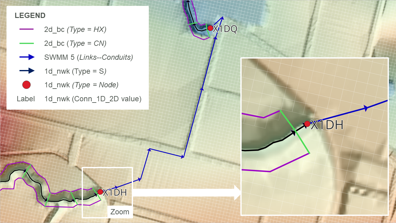
Figure 10.14: SWMM 1D / TUFLOW 1D Connection