4.1 Control Files
The TUFLOW Control files are text files containing a series of commands (instructions) that control how a model is constructed and how a simulation proceeds. They are easily scripted and interpreted, typically short in length, and very powerful for enabling efficient workflows.
This overview chapter discusses:
- Rules and notation in regards to control files (Section 4.1.1),
- Absolute and relative file paths (Section 4.1.2),
- The available units (e.g. Metric or Imperial) (Section 4.1.3), and
- The control files (Section 4.1.5 to Section 4.1.17).
Table 4.1 lists the available control files, provides a brief description and a link to the respective section of this Chapter that discusses the individual control file.
| Control File | Description | Section |
|---|---|---|
| TCF | The TUFLOW Control File (.tcf) file sets simulation parameters and directs input from other data sources. It is the top of the tree, with all input files accessed via the .tcf file or files referred to from the .tcf file. Each TUFLOW simulation must have a .tcf file. | Section 4.1.5 |
| ECF | The ESTRY Control File (.ecf) includes all of the 1D files and commands. 1D commands can also be embedded into the .tcf file should the modeller prefer. | Section 4.1.6 |
| TBC | The TUFLOW BoundaryControl File (.tbc) includes commands related to internal and external boundaries and linking of 1D/2D. | Section 4.1.7 |
| TGC | The TUFLOW GeometryControl File (.tgc) includes commands and geometric / topographic data inputs to build the 2D domain. | Section 4.1.8 |
| QCF | The Quadtree Control File (.qcf) includes the commands required to build a quadtree mesh. | Section 4.1.9 |
| TEF | The TUFLOW Event File (.tef) includes a database of .tcf and/or .ecf commands related to specific events. | Section 4.1.10 |
| TOC | The TUFLOW Operational Control File (.toc) includes operating rules that can be applied to hydraulic structures, pumps and other controllable devices modelled as 1D elements. | Section 4.1.11 |
| TRFC | The TUFLOW Rainfall Control File (.trfc) includes commands to generate rainfall grids based on point rainfall gauges. | Section 4.1.12 |
| TESF | The TUFLOW External Stress File (.tesf) includes commands to define time varying global or spatially varying external forces such as wind or wave radiation stresses. | Section 4.1.13 |
| ADCF | The Advection Dispersion Control File (.adcf) includes the commands required for AD model execution. | Section 4.1.14 |
| TSCF | The TUFLOW SWMM Control File contains the relevant commands needed to manage the SWMM simulation. | Section 4.1.15 |
| Read File | A TUFLOW Read File is a file included inside another file. Any file extension be used, with .trd traditionally used for 2D commands and .erd for 1D. Read files are useful for commands that are common to multiple simulations or for commands that are rarely or never changed and can be placed into another file to reduce the size of the parent file. Up to 9 levels of read files can be nested. | Section 4.1.16 |
| Override File | Override Files allow the user to apply .tcf commands after TUFLOW has finished processing the commands which are referenced within the .tcf file. | Section 4.1.17 |
4.1.1 Rules and Notation
Control files, such as the TUFLOW Control File (TCF), TUFLOW Boundary Control (TBC) and TUFLOW Geometry Control (TGC), are command or keyword driven text or script files. The commands are entered free form, based on the rules described below. Comments may be entered at any line or after a command. The commands are listed in Appendix A to Appendix I.
Note: TUFLOW control files and commands are NOT case sensitive.
An example of a command is:
This command sets the simulation start time to 10 hours. The text to the right of the “!” is treated as a comment and not used by TUFLOW when interpreting the line.
Automatic colour coding (as shown in the above example) of files for easy interpretation is available, with download links and installation instructions, for the following text editors: Notepad++, UltraEdit and TextPad.
Commands can be repeated as often as needed. This offers significant flexibility and effectiveness when modelling, particularly in building 1D and 2D model topography. Note that a repeat occurrence of a command may override the effect of previous occurrence(s) of the same command.
The style of input is flexible bar a few rules. The rules are:
- A few characters are reserved for special purposes as described in Table 4.2;
- Command syntax is not case sensitive;
- Only one command can occur on a single line; and
- A few commands rely on another command being previously specified. These are documented where appropriate.
Additional text can be placed before and/or after a command. For example, a line containing the command Start Time to set the start time of a simulation to 10 hours can be written as:
The (h) text is not a requirement but is useful to indicate that the units are hours. Alternatively, the following would also be acceptable, noting the use of the comment delimiter “!”:
Blank lines are ignored. Spaces or indentations can occur at the start of the line. This is recommended when using the logic control, as outlined in Section 13.2. The second line in the following example is not required to be indented, however, it is strongly recommended to facilitate easy interpretation:
The notation used to document commands and valid parameter values in Appendix A to Appendix I are presented in Table 4.3.
| Reserved Character(s) | Description |
|---|---|
| “#” or “!” | A “#” or “!” causes the rest of the line from that point on to be ignored. Useful for “commenting-out” unwanted commands, and for all that modelling documentation. |
| == |
A “==” following a command indicates the start of the parameter(s) for the command. Where there is more than one parameter, the parameter values are read as free-field formatted, i.e. are space or comma delimited. When processing command line syntax within the control files (.tcf, .tgc, .ecf etc.), if a “==” is not present in the command line syntax TUFLOW will produce an ERROR 0060. For example “ |
| Documentation Notation | Description |
|---|---|
| < … > | Greater than and less than symbols are used to indicate a variable parameter. For example, the commonly used <file> example is described below. |
| <file> | A filename (can include an absolute or relative path, or a UNC path). See Section 4.1.2 for a more detailed description. |
| [ {Op1} | Op2 ] |
The square brackets “[” and “]” surround parameter options. The “|” symbol separates the options. The “{” and “}” brackets indicate the default option. This option is applied if the command is not used. For example, the options for the Maximums and Minimums command are: |
| spaces |
Spaces can occur in commands and parameter options. If a space occurs in a command, it is only one (1) space, not two or more spaces in succession. Spaces can occur in file and path names; however, third party software may not allow this and as such is not recommended. If using spaces in filenames, batch files will require that the filename is enclosed in quotes. |
4.1.2 File Paths
TUFLOW control files reference additional files, for example GIS files. The three methods that can be used are absolute file path, relative file path and UNC file path referencing. A model can use any or all these methods. However, relative file paths are typically preferred.
Note: Depending on the operating system, file paths may be case sensitive.
Take an example of reading a GIS layer containing initial water levels, the command is
- Absolute file path:
Read GIS IWL == L:\Job\Job1234\TUFLOW\model\gis\2d_IWL_001_R.shp
- Relative file path:
Read GIS IWL == ..\model\gis\2d_IWL_001_R.shp
- UNC file path:
Read GIS IWL == \server1\Job1234\TUFLOW\model\gis\2d_IWL_001_R.shp
For the relative file path, the path is relative to the file that is referring to it. In the case above, if the command occurred in the .tcf file, which is in the TUFLOW\runs\ folder, the ..\ indicates to go up one level (from TUFLOW\runs\ to TUFLOW\ the model\ navigates into the TUFLOW\model\ folder, gis\ navigates from TUFLOW\model\ into TUFLOW\model\gis\). To go up more than one level simply use ..\ multiple times (e.g. ..\..\ would navigate up two folders). If the file sits under the same folder, then the filename can be specified. In the below example the Model_Events.tef would need to sit in the same location as the .tcf.
The paths are relative to the current control file, a command in the geometry control file (TUFLOW\model\) would be relative to the .tgc location, not the .tcf location.
Using relative file paths has the advantage that the model can be moved or provided to another user and the control files do not need to be updated, if the model uses an absolute or UNC file path, all references will need to be updated if the model is moved.
Some large files may still use an absolute or UNC file path particularly where large datasets are shared across models. This avoids the need to copy the dataset into multiple projects. An example is:
If using LINUX at any point during the modelling tasks or pre/post processing, it is recommended to set
4.1.3 Units
The default unit settings for all inputs in a TUFLOW model are metric, however, it is possible to create models using US Customary units (also known as Imperial or English units) by specifying the .tcf command
This manual uses the metric term for documentation purposes. If your model uses US Customary Units any user defined values must also be specified in US Customary units. The metric unit and the equivalent US Customary unit are listed in Table 4.4, unless otherwise stated within this Manual. Model units can be checked by searching for the relevant parameter in the .tlf file (refer to Section 14.3).
Output units are listed in Table 11.4.
An example model using the
| Metric | US Customary |
|---|---|
| m | ft |
| mm | inches |
| km2 | miles2 |
| kg | pound |
4.1.4 Mathematical Operations
From the 2025.2.0 release onwards, mathematical operations are supported in TUFLOW control (.tcf, .ecf, .tbc, etc), material and soil (.tsoilf) files. These operations are included using
Mathematical operations must be read and evaluated at the start of the simulation and are not re-evaluated during the simulation. As such,
Example 1: Unit conversion
Example 2: Using variables
If one or more variables are defined in the .tcf (see Section 13.2.3), they can then be adjusted (in the .tcf or in other files) using
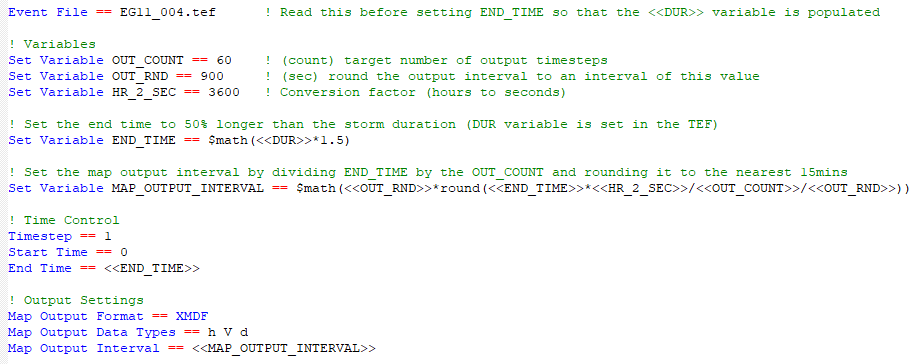
Example 3: Adjusting event variables
Event variables can be adjusted using
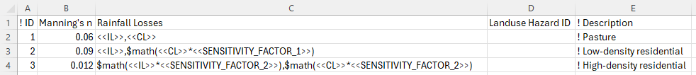
Example 4: ARR losses
If ARR data provides Initial Loss (IL) and Continuing Loss (CL) values directly, but scaled losses are required for certain land uses (e.g. 50% impervious for low-density residential), multipliers can be applied directly or using a variable.
In the .tcf, set sensitivity factors for different land uses:
In the materials file:
Example 5: Logic control
Example 6: Invalid use case
The following .toc file commands are invalid and will result in an error as
4.1.5 TCF - TUFLOW Control File
The TUFLOW Control File (.tcf) file sets simulation parameters and directs input from other data sources. It is the top of the tree, with all input files accessed via the .tcf file or files referred to from the .tcf file. Each TUFLOW simulation must have a .tcf file. An example of a simple .tcf file is shown in Figure 4.1.
The .tcf file must reference the following items as a minimum requirement (TUFLOW won’t run without them):
- Geometry Control File (Section 4.1.8)
- BC Control File (Section 4.1.7)
- Start Time
- End Time
- Map Output Interval
Recommended or most commonly used .tcf commands are:
- Read Materials File
- BC Database
- Solution Scheme
- ESTRY Control File (Section 4.1.6)
- Quadtree Control File (Section 4.1.9)
- SHP Projection/GPKG Projection/MI Projection
- Timestep
- Output Folder
- Map Output Data Types
- Time Series Output Interval
- Write Check Files and
- Write Empty GIS Files.
Commonly used or useful .tcf commands are: BC Event Source; Event File, Read File, Cell Wet/Dry Depth; Instability Water Level; Read GIS FC; Read GIS IWL; Read GIS PO; Screen/Log Display Interval; Set IWL; Start Map Output; Start Time Series Output.
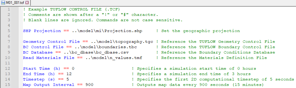
Figure 4.1: Example of a Simple TCF
Appendix A lists and describes .tcf commands and their parameters.
Note that it is possible to incorporate 1D (.ecf) commands into the .tcf file. 1D (.ecf) commands can be included in the .tcf file between Start 1D Domain and End 1D Domain block(s). For the .tef file, 1D (.ecf) commands must be prefixed by “1D”. Also note that ESTRY Control File command is recognised every time if specified more than once.
4.1.6 ECF - ESTRY Control File
Commands specific to TUFLOW (ESTRY) 1D domains are detailed in Appendix B, and can be placed either in the .tcf file (or in a Read File), or in their own file traditionally called an .ecf file. 1D commands can be located:
- Within an .ecf file and referenced within the .tcf file using the command ESTRY Control File. The command ESTRY Control File Auto can be used to force the .ecf file to have the same name as the .tcf file.
- Placed within a 1D domain block in the .tcf using Start 1D Domain and End 1D Domain commands.
- Placed anywhere in the .tcf file and preceded by “1D”, for example, 1D Manhole Default Type. “1D” must be the first two characters.
- Any combination of the above, however, it is strongly recommended in the interests of manageability that a logical approach be adopted (that agrees with your colleagues!).
The .ecf file method is typically used if the 1D domain is large and complex, whereas the 1D domain block or preceding “1D” may be used where the 1D/2D linked model requires only a few 1D commands or they are placed in another file and referenced using Read File.
The 1D commands set simulation parameters and directs input from other data sources for all 1D domains. An example of some 1D commands are shown in Figure 4.2.
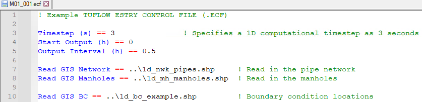
Figure 4.2: Example of a Simple ECF
Appendix B lists and describes the 1D commands and their parameters. Commands that are only relevant for 1D only models are indicated with a “1D Only” underneath the command in Appendix B.
Note: At present it is not an option to truly have a 1D only model. For 1D only models, a single 2D model, which can be made up of a single inactive 2D cell, is still required.
4.1.7 TBC - TUFLOW Boundary Control File
The TUFLOW Boundary Control (.tbc) file contains information regarding the location and type of boundaries within the model. These include (but are not limited to) upstream and downstream boundaries as well as 1D/2D or 2D/2D links. The GIS layers read into the .tbc file reference the Boundary Condition (BC) Database (see Section 8.5). The BC Database associates the GIS layers with a boundary condition such as a hydrograph or a depth-discharge curve.
Only one .tbc file per 2D domain can be specified in the .tcf file using the BC Control File command. A .tbc file must be specified, if no external boundaries are to be applied a blank file may be specified. This is rarely done but can be used for models based only on initial water levels.
Appendix D lists and describes .tbc commands and their parameters.
4.1.8 TGC - TUFLOW Geometry Control File
2D domains are defined through a series of commands contained in TUFLOW Geometry Control (.tgc) files. The .tgc file contains, or accesses from other files, information on the size and orientation of the grid, grid cell codes (whether cells are active or inactive), bed/ground elevations, bed material type or flow resistance value, and optional data such as soil type.
A 2D domain is automatically generated as a grid of square cells. Each cell is given characteristics relating to the topography such as ground/bathymetry elevation, bed resistance value and initial water level, etc.
A .tgc file is specified in the .tcf file using Geometry Control File. For a TUFLOW Classic Multiple 2D Domain model, a separate .tgc file is required for each of the 2D domains, see Section 10.7.2.
Rather than contain all the 2D grid information in one file, the .tgc file is a series of commands that builds the model. The commands are applied in sequential order. It is possible to override previous information with new data to modify the model in selected areas. This is extremely useful where a base dataset exists, over which areas need to be modified to represent other scenarios such as a proposed development. This eliminates or minimises data duplication.
The commands can occur in any order (as long as it is a logical one).
If an unrecognisable command occurs, TUFLOW stops and displays the unrecognisable text.
Notes & Tips:
- Commands can be repeated any number of times.
- Commands are executed in the order they occur. If the data for a 2D cell or Zpt is supplied more than once, the last data that is read is used (i.e. the latter data for a cell overrides any previous data for that cell).
- Each data layer does not have to cover the entire model – only the 2D cells influenced by the objects in the layer (e.g. a 3D breakline) are affected.
- Use Write Check Files commands to cross-check and carry out quality control checks on the final 2D grid, elevations, material or land-use categories, etc.
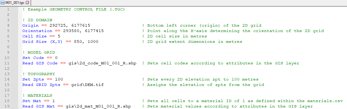
Figure 4.3: Example of a Simple TGC
Appendix C lists and describes .tgc commands and their parameters. An example of a .tgc file is shown in Figure 4.3.
4.1.9 QCF - Quadtree Control File
For a quadtree grid, the Quadtree Control File (.qcf) is used to define the grid refinement areas and optionally the model location and extent, see Section7.3.1. A .qcf file is specified in the .tcf file using the Quadtree Control File command.
For a quadtree grid, only one .tgc file can be specified that covers all the 2D cell resolutions. The .qcf file primarily controls the nesting levels of different 2D cell resolutions, but may also control the overall grid orientation and location instead of the .tgc file. An example of setting up a model to use a quadtree grid is provided in TUFLOW Tutorial Module 7.
Appendix H lists and describes .qcf commands and their parameters.
4.1.10 TEF - TUFLOW Event File
The TUFLOW Events File (.tef) contains a database of .tcf and .ecf file commands for different events. A .tef file is specified in the .tcf file using the Event File command. Events are set up using a define event block, for example:
Event management is a powerful functionality that allows running multiple event combinations (e.g. magnitude, duration, temporal patterns, climate change) using a single set of control files rather than creating a new set of control files for every simulation. This makes the management of the model easier, ensures consistency between the simulations, and better quality control. An example of the number of .tcf and bc_database files required for a model with and without event management is shown in Figure 4.4.
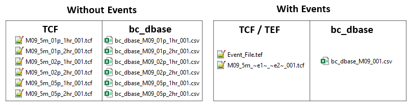
Figure 4.4: Reduction of Control Files using Event Management
Event management is detailed in Section 13.2.1. An example of setting up a model to use event management is provided in TUFLOW Tutorial Module 9.
4.1.11 TOC - TUFLOW Operations Control File
The TUFLOW Operations Control (.toc) contains operating rules for structures. A .toc file is specified in the .ecf file using the Read Operating Controls File command, or in the .tcf file within a Start 1D Domain block. Operational Channels are detailed in Section 5.9. An example of its use is provided in TUFLOW Tutorial Module 10 Part 3.
Appendix E lists and describes .toc commands and their parameters.
4.1.12 TRFC - TUFLOW Rainfall Control File
The TUFLOW Rainfall Control File (.trfc) contains commands used to generate rainfall grids based on point rainfall gauges. This approach generates a series of rainfall grids available to the user for display or checking. A .trfc file is specified in the .tcf using the Rainfall Control File command. An example of its use is provided in TUFLOW Tutorial Module 6 Part 3.
Appendix F lists and describes .trfc commands and their parameters.
4.1.13 TESF - TUFLOW External Stress File
The External Stress File (.tesf) allows the definition of time varying global or spatially varying external forcing such as wind or wave radiation stresses. A .tesf file is specified in the .tcf using the External Stress File command. External stress boundaries are discussed in Section 8.7.
Appendix G lists and describes .tesf commands and their parameters.
4.1.14 ADCF - Advection Dispersion Control File
The Advection Dispersion Control File contains commands related to the TUFLOW Advection Dispersion (AD) Module for simulating depth-averaged, constituent fate and transport. The .adcf is specified in the .tcf using the AD Control File command. The Advection Dispersion module is discussed in Chapter 9.
Appendix J lists and describes .adcf commands and their parameters.
4.1.15 TSCF - TUFLOW SWMM Control File
TUFLOW 2D domains can be dynamically linked to SWMM’s 1D solution scheme. The TUFLOW SWMM Control File (.tscf) contains the SWMM input commands. The .tscf file is specified in the .tcf using the SWMM Control File command. Section 10.4 provides information on linking to the 1D scheme, and examples are given in the TUFLOW-SWMM Tutorial Modules.
Appendix I lists and describes .tscf commands and their parameters.
4.1.16 Read File
The Read File command is extremely useful for placing commands that remain unchanged or are common for a group of simulations in another file (e.g. the SHP Projection command will be the same for all runs within the same study area). This reduces the size/clutter of .tcf files and allows easy global changes to a group of simulations to be made.
The file extensions most commonly used are .trd (2D commands), .erd (ESTRY 1D commands) and .rdf.
4.1.17 Override Files
These optional override files allow the user to apply .tcf commands after TUFLOW has finished processing the commands referenced within the .tcf file. This can be useful where you wish to change a parameter for all simulations that are started from a common folder. For example, you could turn off check files, or change the output drive.
Two override file types are possible, one which is computer specific and one which is processed by all computers. If either or both are present, they are processed after all the .tcf file commands have been processed so that the override commands prevail.
The first override file that TUFLOW checks for is named “_TUFLOW_Override.tcf”. If this file exists within the same folder as the .tcf file, .tcf commands that are listed within the “_TUFLOW_Override.tcf” file overwrite the commands in the .tcf file.
The second one TUFLOW looks for must be named “_TUFLOW_Override_<computer_name>.tcf”, where <computer_name> is the name of the computer running the simulation. If this file exists TUFLOW will process any commands within it after any commands from the “_TUFLOW_Override.tcf” file (if it exists). If you are unsure of your computer name, this is displayed in the computer’s properties or in a TUFLOW Log File (.tlf) that has been processed on that computer, this is typically at the top of the .tlf (line 6). For example:
With the computer name above the computer specific override file would be named “_TUFLOW_Override_COMP1234.tcf”.
An override file specific to a particular computer can be particularly useful where, for example, different output drives or results folders, are to be used for runs using different computers. This will allow you to run TUFLOW simulations on different computers without having to change the .tcf file.
For example, if a run is started on one machine that only has a C drive, output can be directed to the C drive just for that computer by using the command
Another example is if using the GPU solver and one machine only has a single GPU, while another has four GPUs. The command
Nearly all .tcf commands can be placed within the override files except for “Read GIS” and some other similar commands that involve processing of data layers. It is recommended that the override files are only used for global changes to settings, similar to the examples above.