16.4 Models Exceeding Hardware RAM
In some situations TUFLOW modellers may experience an error due to the model simulation requiring more Random-Access Memory (RAM) than is available in the computer. When this situation occurs the following message is reported.
Figure 16.5: TUFLOW RAM Error
The error may be caused by a number of contributing factors. The following sections discuss the common causes and recommended troubleshooting considerations to help resolve the issue.
16.4.1 Computer RAM
If a TUFLOW simulation can not allocate sufficient RAM the first check that should be made is the amount of available RAM on the computer. What are the computers specifications and what is already being used by other processes? This can be done in Windows Task Manager. Third party software used to build TUFLOW models and view their results (such as GIS or CAD packages) can consume large amounts of RAM, leaving little remaining for the TUFLOW simulation.
16.4.2 TUFLOW Version
The choice of TUFLOW version can influence the amount of RAM needed to simulate the model. The double precision (DP) versions of TUFLOW utilise more RAM (up to twice as much) than the single (SP) precision version, as all real numbers are 8-byte reals in the DP version, rather than 4-byte reals in SP. Refer to Section 13.3.2 for further information on the difference between single and double precision versions of TUFLOW.
16.4.3 Model Design
Key model design items that influence memory allocation, and should be reviewed if simulation RAM requirements need to be reduced, include:
- The size of the redundant area around the perimeter of the active model domain;
- The number of 2D cells, hence the domain extent and the cell size; and
- Choice of model features utilised.
The term, “redundant area” is defined as the difference between the 2D domain size and the active model area. As discussed in Section 7.2.2, TUFLOW automatically strips any redundant rows/columns around the active area of the model to reduce simulation times, this however does not reduce the amount of RAM consumed by the model. Refer to Sections 7.2.1 and 7.2.2 for further information on defining the 2D domain and the active/inactive areas of a model.
Figure 16.6 presents two different versions of an example model. The only difference between both models is the size of the 2D domain. The 2d_dom check file of the models has been overlaid on top of the active area of the model, represented by a magenta polygon (2d_code GIS layer with CD=1).
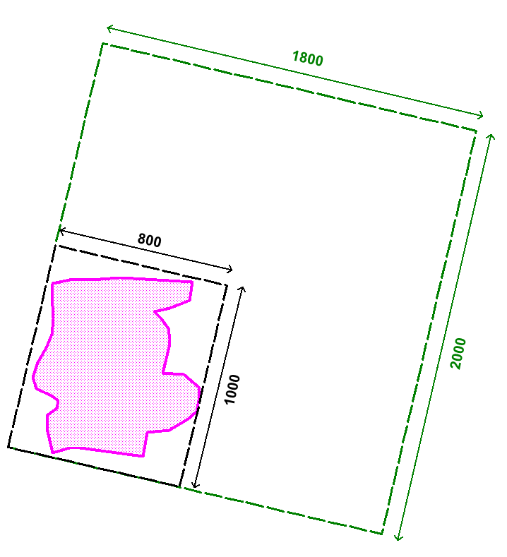
Figure 16.6: Influence of 2D Domain Size on RAM Allocation
In this example, the green coloured 2d_dom_check in Figure 16.6 has been defined using
the .tgc command
In contrast the black coloured 2d_dom_check area in Figure 16.6 shows a much better fit to the active area. This model domain has been defined using the .tgc command
The size of the redundant area can be determined by searching within the .tlf file for the term “redundant”.
For larger (green) domain in the figure above, the tlf file states the following redundant area information.
Isolating redundant perimeter sections of 2D domain Domain_001…
…Reduced computational grid by 79%. Now extends from [5,7] to [196,169].
…Reduced output grid by 79%. Now extends from [5,7] to [196,169].
It indicates TUFLOW has reduced the computation grid by 79%, meaning the active area is only 21% of the size of the 2D domain! A search for “memory” in the .tlf file shows the required memory allocation for the model:
Memory requested for 2D domain Domain_001 = 101 Mb
Total Memory requested thus far = 104 Mb
For smaller (black) domain in the figure above, the tlf file states the following redundant area information.
Isolating redundant perimeter sections of 2D domain Domain_001…
…Reduced computational grid by 8%. Now extends from [5,7] to [196,169].
…Reduced output grid by 8%. Now extends from [5,7] to [196,169].
The smaller 2D domain also has a noticeable impact on the memory required to run the model. In this case, reducing it by a factor of 5, from 104Mb to 27Mb.
Memory requested for 2D domain Domain_001 = 23 Mb
Total Memory requested thus far = 27 Mb
The 2D cell size dictates the total number of cells within a given study area, keeping in mind that halving the cell size quadruples the number of cells. The number of cells has a direct correlation to the amount of RAM required to run the model. For each cell, TUFLOW stores a number of variables including depth/water level and velocity components. The greater the number of cells, the greater the amount of information stored and the greater the amount of memory needed to simulate the model. Simulating a variety of models, each with a different cell size during the initial model development stage, will provide a modeller with an understanding of the impact the cell size has on simulation time, memory allocation and also model results. Refer to Section 3.2.4 for discussion on cell size convergence testing.
A number of optional TUFLOW features may also increase the simulation memory requirements. Common features include:
- Model Output Zones (Section 11.2.5). Adding Extra Output Zones will increase the RAM requirement.
- TIF, ASC or FLT grid raster Map Output Format (Section 11.2.2). Consider using these grid raster output types for maximum reporting only. Use the XMDF or CC format for time varying dynamic 2D Map Outputs.
- Direct rainfall boundary condition inputs defined using the Read GIS RF format can require significant amounts of RAM. Consider using a Rainfall Control File approach to define the input instead. It requires a far smaller amount of memory.
- Excessively fine TUFLOW HPC sub-grid sampling resolution.
16.4.4 Memory Usage Reporting
The TUFLOW log file (.tlf) provides a summary of the model’s memory usage. The memory usage information can be used to identify which items of a model require the most RAM. An example is provided below:
1D QX and HX BCs automatically detected
1D Geometry data memory …….. 18 Mb
1D Boundary data memory …….. 0 Mb
1D yQ Curves memory ………… 0 Mb
1D Control structures memory … 0 Mb
1D Mesh data memory ………… 3 Mb
1D Results storage memory …… 24 Mb
1D Temporary data memory ……. 8 Mb
1D Computational arrays memory . 0 Mb
Total 1D domain memory (RAM) requested ………… 54 Mb
Total 1D domain character memory (RAM) requested .. 7 Mb
Domain_001 : Allocating Memory Pointers:
Domain_001 : Grid data memory …………… 47 Mb
Domain_001 : Variable Z and Layered FC memory 0 Mb
Domain_001 : Sub-domain linking memory …… 4 Mb
Domain_001 : Flow constrictions memory …… 16 Mb
Domain_001 : Weirs and viscosity factor memory 14 Mb
Domain_001 : Pressure, wind and waves memory 0 Mb
Domain_001 : General Memory …………….. 14 Mb
Domain_001 : Boundary conditions memory ….. 7 Mb
Domain_001 : Wind & waves boundary memory … 0 Mb
Domain_001 : Work arrays memory …………. 115 Mb
Domain_001 : SMS High Res format memory ….. 0 Mb
16.4.5 Temporary Memory Usage
A number of input steps may require additional memory for processing during model initialisation. For example, when a large DEM is input (Read Grid Zpts), this is read into memory and then processed. This allows for a very rapid processing of the file, though may consume significant additional memory. The DEM can be tiled to reduce memory usage at start-up. Other files that consume additional memory are Read GIS Z Shape, as TUFLOW tracks the modified elevation and the change in elevation for all Zpts.
The Maximum Vertices and Maximum Points commands can be used to increase or decrease the size of a single GIS object and will change the memory required.
For models utilising TUFLOW HPC Sub-Grid Sampling (SGS) with the SGS Approach Method A or B (default prior to 2023-03), the sub-grid sampling was undertaken during the data pre-processing, though the raw input data not retained. In the 2023-03 TUFLOW release, a new and improved Method C approach (default in 2023-03 and later) was introduced. Method C retains the raw sub-grid sampled elevation information from the pre-processing stage for numerous post-processed result features. Whilst Method C can potentially use more RAM, the approach has considerable benefits in terms of preserving sub-grid elevation data at cells/faces partially affected by terrain data layers and allows TUFLOW to produce high-resolution mapping at the SGS sampling resolution.
Sub-grid sampling is a computationally intensive process, particularly for large models with small SGS sample distances. To speed up model initialisation, TUFLOW has been configured to utilise multiple CPU cores. By default, all CPU threads will be used for final SGS elevation pre-processing unless the number of threads (-nt[thread count]) command line argument has been specified. For example, to run on 8 threads the command line argument “-nt8” would be used. There is no check for thread licensing used for pre-processing. All threads are used if the number of threads specified in the command line argument exceeds the number of threads available.
In addition to the parallelisation of the final SGS elevation pre-processing, XF files are now supported for SGS Method C. At the end of the .tgc reading, after all elevation datasets have been processed, an XF file is written if the XF Files command is set to on (default). This XF file can then be utilised in subsequent simulations, reducing memory requirements and processing time.
16.4.6 TUFLOW HPC GPU Module and RAM requirements
When running TUFLOW HPC with the GPU Module, TUFLOW Classic carries out all the pre- and post-processing of the data (setting up the model and storing and tracking of all output data). These CPU tasks typically consume significantly more memory than that required to carry out the hydraulic computations on the GPU card. Although the hydrodynamic calculations are carried out on the GPU card/s, significant amounts of CPU RAM are also required. As a rough guide, the CPU RAM requirement is around 4 to 6 times that of the GPU memory (with grid based output active and set to the defaults).