5.8 Special Channels
5.8.1 M Channels (User Defined Flow Matrix)
M channels allow the modeller to define the flow through a channel (usually a structure) based on a user specified flow matrix. To set up M channels follow the steps below:
- In the 1d_nwk layer, populate the required attributes as shown in Table 5.19
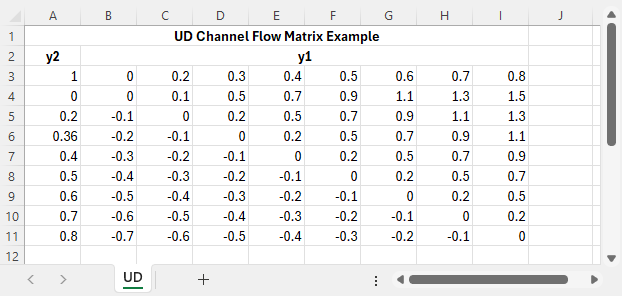
- Create the flow matrix as shown in the image below and save the file as a .csv. The .csv file is referenced in the 1d_nwk Inlet_Type attribute. Notes using the example in the
below image are:
- TUFLOW searches through the sheet until more than 3 numbers are found at the beginning of a row (Row 3 in the example).
- This first row contains a multiplication factor (in Cell A3) followed by upstream depth values (in the direction that the channel is digitised). The depth values are added to the channel invert to set the water level.
- The next rows have the downstream depth in Column A. Flows are listed in the adjacent columns relating to the above upstream depth value (Row 3).
- Note: at present the matrix must be square and that the u/s and d/s depths must be the same values. The flows along the diagonal must be zero, and to the left of the diagonal negative (or zero) and to the right positive (or zero).
- TUFLOW searches through the sheet until more than 3 numbers are found at the beginning of a row (Row 3 in the example).
- Optionally create a flow area matrix of the same dimensions and depth values as for the flow matrix. Note:
- The path to the area.csv file is specified after the flow.csv file in the Inlet_Type attribute (separate the two filenames using a “|”; eg. “..\UD_Q.csv | ..\UD_A.csv”).
- The factor value in the A3 cell is not used in the flow area matrix (the value in the flow matrix is used to factor the areas).
- The area values are only used for outputting the channel velocity (they are not used for the hydraulic computations other than when the channel velocity is used for other channels, eg. adjusting structure losses).
- If an area matrix is not provided, TUFLOW will calculate the area based on the channel width multiplied by the pBlockage and the average of the upstream and downstream depths.
- The path to the area.csv file is specified after the flow.csv file in the Inlet_Type attribute (separate the two filenames using a “|”; eg. “..\UD_Q.csv | ..\UD_A.csv”).
A working example of a model containing a 1D M channel is provided in the 1D Structures Example Model Dataset on the TUFLOW Wiki.
5.8.2 Q Channels (Upstream Depth-Discharge Relationship)
Q channels are used to model flow through a channel using an .ecf Depth Discharge Database. The Depth Discharge Database is the same as the Pit Inlet Database used for Q pits, with the same database used for both Q channels and Q pits. Refer to Section 5.10.3.
In the 1d_nwk layer, the following attributes can be used to set up a Q channel (also see Table 5.19).
- ID = Unique Channel ID.
- Type = “Q”.
- US_Invert = Elevation corresponding to zero depth in the
depth-discharge curve.
- Inlet_Type = The depth discharge curve in the Depth Discharge Database or Pit Inlet Database. This is analogous to a Q pit (see Section 5.10.3). Note that the flow is automatically adjusted for being drowned out using the Bradley relationship for weirs (see Section 5.7.4.2 or Figure 5.7), and if the flow reverses the same depth discharge curve is used.
- Width_or_Dia = For Q channels can be used as a flow multiplier – this is useful if the depth-discharge curve is a unit flow (i.e. flow per unit width). If the discharge is unit flow specify the width of the flow, otherwise specify a value of 1.0 (noting that a zero value is treated as 1.0).
- Number_of = The number of parallel Q channels (a zero value is interpreted as one channel).
A working example of a model containing a 1D Q channel is provided in the 1D Structures Example Model Dataset on the TUFLOW Wiki.
5.8.3 X Connectors
X connectors are used for connecting a side tributary or pipe into the main flow path. They are digitised as a line within a 1d_nwk GIS layer with type “X”. No other attributes are required.
Use of an X connector has the advantage of allowing different end cross-sections (see Section 5.6.6) or WLLs (see Section 11.2.4) to be specified for the side channel, rather than using the end cross-section on the main channel.
They can also be used in pipe networks to ensure that the angle of the inlet and outlet culverts has been digitised appropriately as this influences the manhole losses calculated when using the Engelund loss approach (see Section 5.10.4.4). The angle of the pipe channel line is used for determining manhole losses, not that of the X connector.
The direction of the X Connector must be digitised starting from the side channel and ending at the main channel. If two or more connectors are used at the same location (i.e. to connect two or more side channels to a main channel) their ends must all snap to the same main channel.
5.8.4 Legacy Channels
For backwards compatibility, gradient (type ‘G’) and normal (type ‘blank’) channels remain supported in the current release of TUFLOW. Sloping (type ‘S’) open channels are the preferred method of modelling open channels as it incorporates the flow regimes covered by normal and G channels and include the additional ability of handling super-critical flow. Refer to Section 5.5 for further information.
A normal flow channel is defined by its length, bed resistance and hydraulic properties. The channel can wet and dry, however, for overbank areas (e.g. tidal flats or floodplains) G or S channels should be used. Note: For open channels it is recommended to use the S Type for the reasons given above.
Gradient channels were designed for overbank areas such as tidal flats and floodplains. The upstream and downstream bed invert attributes must be specified to define the slope of the channel. They are like normal channels, except when the water level at one end of the channel falls below the channel bed, the channel invokes a free-overfall algorithm that keeps water flowing without using negative depths. The algorithm takes into account both the channel’s bed resistance and upstream controlled weir flow at the downstream end.
Note: For overbank areas it is recommended to use the S Type for the reasons given above.
5.8.5 1d_nwk Attributes (M, P, Q, SG, SP Channels)
The table below covers the 1d_nwk attributes for all channels not covered in other 1d_nwk attribute tables.
| No. | Default GIS Attribute Name | Description | Type |
|---|---|---|---|
| 1 | ID | Unique identifier up to 12 characters in length. It may contain any character except for quotes and commas and cannot be blank. As a rule, spaces and special characters (e.g. “\”) should be avoided, although they are accepted. The same ID can be used for a channel and a node, but no two nodes and no two channels can have the same ID. | Char(12) |
| 2 | Type |
The channel type as specified using the flags in Table 5.1. For X (connectors), no other attributes are required. |
Char(4) |
| 3 | Ignore | If a “T”, “t”, “Y” or “y” is specified, the object will be ignored (T for True and Y for Yes). Any other entry, including a blank field, will treat the object as active. | Char(1) |
| 4 |
UCS (Use Channel Storage at nodes). |
M, P, Q Channel Type: If left blank or set to Yes (“Y” or “y”) or True (“T” or “t”), the storage based on the width of the channel over half the channel length is assigned to both of the two nodes connected to the channel. If set to No (“N” or “n”) or False (“F” or “f”), the channel width does not contribute to the node’s storage. See Section 5.12.1.1 for further discussion. |
Char(1) |
| 5 | Len_or_ANA |
M, P, Q Channel Type: Only used in determining nodal storages if the UCS attribute is set to “Y” or “T”. Not used in conveyance calculations. |
Float |
| 6 | n_ nF_Cd |
M, P, Q Channel Type: Discharge coefficient for the structure if using a fixed coefficient. If the value is less than or equal to zero, the default Cd value of 0.6 for SG and 0.75 for SP is used. |
Float |
| 7 | US_Invert |
M Channel Type: P Channel Type: Q Channel Type: US_Invert sets the level from which the upstream depth is to be calculated for interpolation into the depth-discharge curve. SG Channel Type: Sets the spillway crest |
Float |
| 8 | DS_Invert |
M Channel Type: P Channel Type: Q Channel Type: SG Channel Type: Sets the level of the gate seat (if SP is operated, i.e. a SPO channel). |
Float |
| 9 | Form_Loss |
M, P, Q, SP Channel Type: If no weir is specified in the Type attribute, it is assumed that the gate seats on to the bottom of the channel. For this case the flow calculations where the gate is not surcharged uses the Form_Loss attribute to apply an energy loss to the structure to represent contraction/expansion losses. |
Float |
| 10 | pBlockage |
Q Channel Type: M Channel Type: The channel’s dimensions and flow capacity are reduced as per the pBlockage value. |
Float |
| 11 | Inlet_Type |
M Channel Type: P, SG, SP Channel Type: Q Channel Type (for QO see further below): For operated Q channels the filename of a .csv file containing a flow matrix table in the same format as used for M channels. See Section 5.8.1. |
Char (max 256) |
| 12 | Conn_1D_2D | Not used. | Char |
| 13 | Conn_No | Not used. | Integer |
| 14 | Width_or_Dia |
P Channel Type: M Channel Type: Q Channel Type (for QO see further below): QO Channel Type: The width of the gate/spillway. The flow area is assumed to be rectangular in shape. |
Float |
| 15 | Height_or_WF |
M, Q Channel Type: P Channel Type: SG Channel Type: For an operated (gated) spillway (SPO), sets the vertical height of the gate in its fully open position. The fully open height can also be changed during the simulation using the .toc file operating control commands. This is useful where the operating control definition is generic (i.e. non-structure specific). Not used if channel is non-operational (i.e. a SP channel). |
Float |
| 16 | Number_of |
P, SG, SP Channel Type: Number of parallel channels (flow and area matrices are multiplied by this value). If zero is set to one. |
Integer |
| 17 | HConF_or_WC |
M, Q Channel Type: SP Channel Type: \[Q = \frac{2}{3}\:C_{sf}\:C_{d}\:B\:\sqrt{2g}\:H^{Ex}\] SG Channel Type:As for the weir channel in Table 5.17 if a weir has been specified (e.g. a “SG WB” channel). |
Float |
| 18 | WConF_or_WEx |
M, Q Channel Type: SP Channel Type: As for the weir channel in Table 5.17 if a weir has been specified (e.g. a “SG WB” channel). |
Float |
| 19 | EntryC_or_WSa |
M, Q, SPO Channel Type: SP Channel Type: \[C_{sf} = \left(1 - \left(\frac{H_{d}}{H_{u}}\right)^a\right)^b\] SG Channel Type:As for the weir channel in Table 5.17 if a weir has been specified (e.g. a “SG WB” channel). |
Float |
| 20 | ExitC_or_WSb |
M, Q, SPO Channel Type: SP Channel Type: As for the weir channel in Table 5.17 if a weir has been specified (e.g. a “SG WB” channel). |
Float |