5.12 Nodes
Nodes must be defined (either automatically or manually) at the ends of channel elements. They provide storage information, and the 1D water level (the mass balance equation) is calculated at the nodes. Nodes are created in several ways:
- Automatically, at channel ends (Section 5.12.1).
- Manually, as digitised points in a 1d_nd or 1d_nwk layer (Section 5.12.2).
- From a pit in a 1d_pit or 1d_nwk layer (Section 5.10.2).
- From a manhole in a 1d_mh layer (Section 5.10.4).
Note: The use of the term “node” in this manual refers to both manually digitised nodes and nodes that are automatically created at the ends of channels where no digitised nodes exist.
Table 5.30 below lists the available node types.
| Channel/Node | Type | Description |
|---|---|---|
| Node |
Node (or leave blank) |
Used for manually assigning nodal storage or invert levels. |
| Circular Culvert | C | Circular (in the vertical) pit channel inlet (see Section 5.10.2.2). |
|
Depth-Discharge Pit or Channel |
Q | A pit channel whose flow is defined by a depth-discharge curve from a database of curves (see Section 5.27). |
| Rectangular Culvert | R | A rectangular (in the vertical) pit channel inlet (see Section 5.10.2.2). |
| Weir | W | A weir (in the vertical) pit channel inlet (see Section 5.10.2.2). |
Storage at a node is defined either:
- automatically via:
- the widths and lengths of the connected channels (see Section 5.12.1);
- the widths and lengths of the connected channels (see Section 5.12.1);
- manually via:
- a combination of the above using the Len_or_ANA attribute to add additional storage to the automatic storage.
All nodes must have their storage defined by one of these approaches.
Note that checks are also made for the following.
- The lowest elevation of a node must be below the lowest channel connected to the node.
- The highest elevation of a node is used to detect instabilities. The highest elevation should be above the highest expected water level, unless Depth Limit Factor is used to extend storage properties above the highest elevation.
- The storage (surface area) of a node must not be zero at any level.
It is important to note the logic in assigning node storage:
- User defined NA tables take precedence (see Section 5.12.2.1). The overwrite principle applies, so that if a NA table has been previously defined, the latter NA table prevails.
- Nodes without any NA tables assigned as for Step 1 above, and which have one or more connected channels that have the UCS attribute left blank or set to “Y” or “T”, have their NA table automatically calculated from the channel widths (see Section 5.12.1.1).
- The Len_or_ANA attribute of a node (or pit) in a 1d_nwk layer can be used to add additional surface area to the NA table. If no NA table exists after the above steps, and the Len_or_ANA attribute is greater than zero, a NA table of constant surface area is created.
- If there are any nodes remaining without a NA table, an ERROR occurs.
5.12.1 Automatically Defined Nodes
If a node has not been digitised at the end of a channel a new node is automatically created. The ID of the automatic node is the first ten characters of the Channel ID with a “.1” or “.2” extension. “.1” is used if the node is at the start of the channel and “.2” if at the end in the direction digitised. If more than one channel is connected to the created node, the Channel ID that occurs first alphanumerically is used. The automatic creation of nodes can be switched off using Create Nodes. If automatic creation of Nodes is turned off, a manually defined node must be specified at the ends of each channel in the model.
The automatic node approach is used in TUFLOW Tutorial Module 5.
The nodal storage for the automatically created nodes consists of 3 parts:
- Storage calculated from channel/pipe widths;
- Storage added from the len_or_ANA attribute of the connected pits/nodes/manholes; and
- Storage above the top of channels (Section 5.12.3).
5.12.1.1 Storage Calculated Automatically from Channel Widths
The channel storage is, by default, automatically assigned to the nodes at the channel’s ends. The channel storage approach is invoked using the 1d_nwk UCS attribute, see Table 5.19. If the attribute is left blank or set to “Y” (yes) or “T” (true), the channel storage is assigned to the two nodes at the channel’s ends, with the storage split equally between the nodes. For each node the surface area at different elevations is calculated as the product of the channel width by half the channel length. The channel slope is taken into account when distributing the storage. This approach applies for both 1D open channel networks and 1D pipe networks.
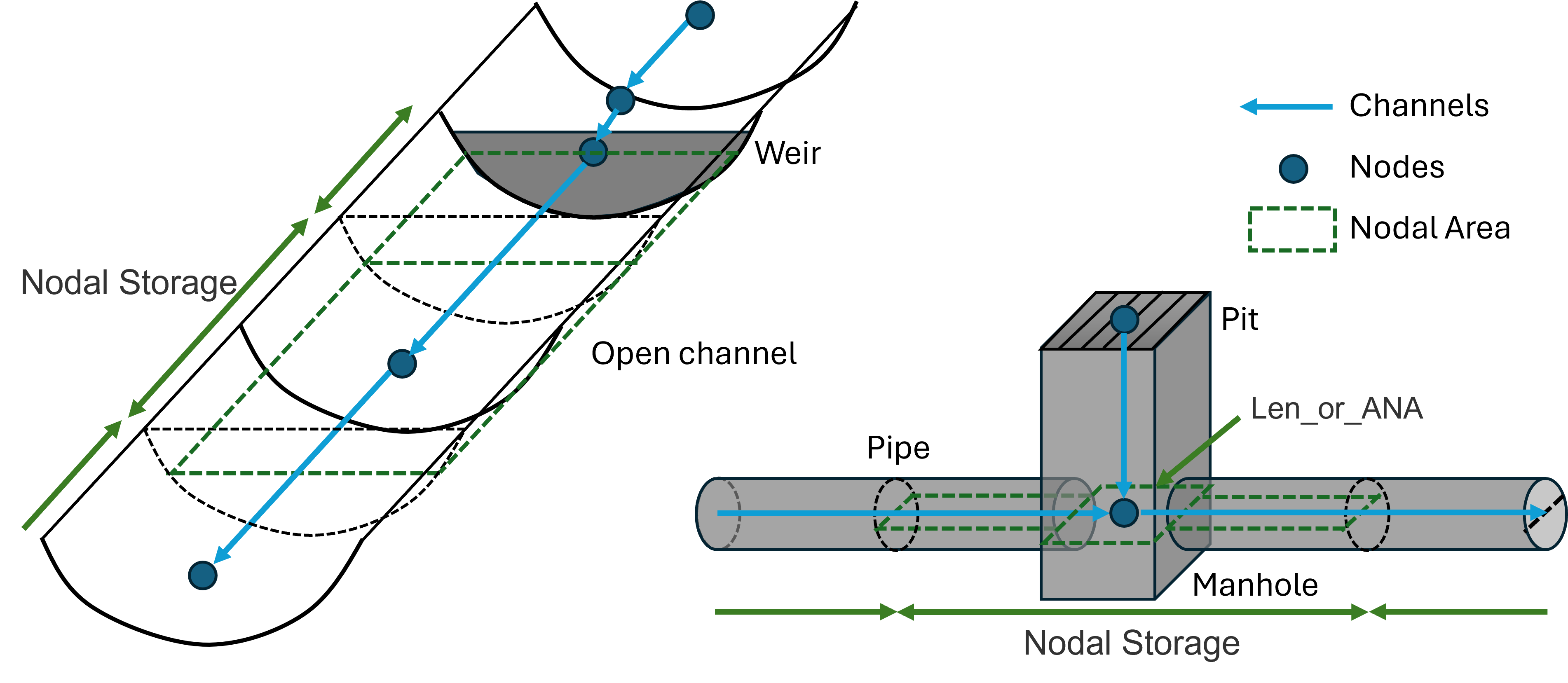
Figure 5.21: Nodal Storage in Open Channel & Pipe Networks
This approach does not require any specification of a NA table and is the easiest to implement. It is suited to open channel or pipe network nodes where the storage is accurately defined using the channel widths. For example, nodes connecting channels that model the in-bank flow paths of a river. It may not be suited to, for example, floodplain areas where the storage may differ significantly from that calculated using the widths of the floodplain channels.
Care should be taken using this option for G or S channels that have very steep slopes – check that the resulting calculated NA table in the .eof file is satisfactory.
Some structures such as pits, weirs, gates and etc., are treated as ‘zero-length’ channel. These channels do not add storage to the connected nodes, unless a non-zero ‘Len_or_ANA’ value is specified (See Section 5.12.1.2).
Nodal storage is not automatically calculated based on the channel width and length if the 1d_nwk UCS attribute is set to “N” (no) or “F” (false). This would require manual specification of an NA table (see Section 5.12.2.1).
5.12.1.2 Additional Storage Added from Len_or_ANA Attribute
The Len_or_ANA attribute can be used to add extra storage to the connected nodes. For example, the Len_or_ANA attribute of a 1D_nwk pit layer can be used to specify the additional nodal storage of a manhole chamber. Similarly, the Len_or_ANA attribute of a 1D_nwk weir layer can be used to set the additional nodal storages of a broad crest weir. This extra storage may also be useful for stabilising a 1D node provided relatively negligible additional amounts of storage are added. Below is the summary of 1D layers that support the Len_or_ANA attribute:
- 1D_nwk pit or node layer;
- 1d_nd and 1d_mh layer;
- 1d_nwk weir, gate, spillway and etc.; and
- 1d_bg layer.
Please see the attribute table of each layer for more details.
Note that a minimum storage area of 1m2 applies to all nodes (except for the upstream (ground) nodes of pit channels) for simulation stability. If any ‘Len_or_ANA’ value is less than 1m2 it might not be reflected in the NA table. This minimum value can be adjusted using the Minimum NA and the Minimum NA Pit commands.
Note: If using imperial units (
5.12.2 Manually Defined Nodes
Table 5.31 lists the attributes required for manually created nodes in the 1d_nwk layer format, used with the Read GIS Network command. Table 5.32 lists the attributes required for manually created nodes in the 1d_nd format with the Read GIS Node command – essentially an updated, cutdown version of the 1d_nwk format that removes unnecessary input fields. Both formats remain supported.
These attribute descriptions are for basic “Node” type 1d_nwk point objects. These may be used for assigning storage and invert levels to channels. They can also be used to automatically link 1D nodes to the 2D domains (without the need to digitise objects within a 2d_bc layer). The 1D/2D link functionality is discussed in detail within Section 10.3.3.
If an ID is specified it must be unique amongst all nodes, and up to 12 characters in length. It may contain any character except for quotes and commas. As a rule, spaces and special characters (e.g. “\”), should be avoided although they are accepted. A node ID can be used for a channel (i.e. a channel and node can have the same ID), but not for another node. The Ignore attribute can be used to ignore a node. It is recommended for the 1d_nwk Type attribute that “Node” is entered to easily distinguish nodes from channels when querying objects in the GIS, or alternatively place the nodes and pits in separate 1d_nwk layers.
This section does not provide information on pit type nodes (C, Q, R or W) that also use the 1d_nwk file format. Refer to Section 5.10.2 for information about pit type nodes.
| No. | Default GIS Attribute Name | Description | Type |
|---|---|---|---|
| 1 | ID |
Unique identifier up to 12 characters in length. It may contain any character except for quotes and commas and cannot be blank. As a rule, spaces and special characters (e.g. “\”) should be avoided, although they are accepted. The same ID can be used for a channel and a node, but no two nodes and no two channels can have the same ID. Digitised nodes can have their ID left blank and TUFLOW will assign an ID. |
Char(12) |
| 2 | Type | Leaving this attribute blank or specifying “Node” will define the point feature as a Node type. “Node” is recommended for easy identification. | Char(4) |
| 3 | Ignore | If a “T”, “t”, “Y” or “y” is specified, the object will be ignored (T for True and Y for Yes). Any other entry, including a blank field, will treat the object as active. | Char(1) |
| 4 | UCS | Not used. | Char(1) |
| 5 | Len_or_ANA |
Adds the value specified as additional nodal area (surface area in m2). If no nodal area data exists for the node, either via the UCS attribute from the connected 1d_nwk channels, or via NA table, TUFLOW automatically creates an NA table of constant surface area set to this value with an elevation range based on the US_Invert and DS_Invert values. If a negative value is specified, the absolute of this value is used as a multiplier of the node storage. For example, a value of -1.5 increases the nodal storage table (NA table) by 50% (or to reduce storage use a value between -1 and 0). Increasing storage can be useful to stabilise problematic 1D nodes, provided that the added storage does not adversely distort the results. This multiplication is applied after any effect of Minimum Channel Storage Length. Minimum NA is applied after the multiplication. |
Float |
| 6 | n_nF_Cd | Not used. | Float |
| 7 | US_Invert | If no NA table exists and Len_or_ANA is greater than zero, used to set the upper elevation of the NA table. Note that in this case if US_Invert is less than DS_Invert, US_Invert is set to the DS_Invert plus 5 metres. | Float |
| 8 | DS_Invert |
If no NA table exists and Len_or_ANA is greater than zero, used to set the bottom elevation of the NA table. Also used to set the upstream and downstream inverts of connected open channels, culverts/pipes and other channel types – as an example see discussion for US_Invert in Table 5.3. Also see Section 5.12.2.2. If set to -99999, not used. |
Float |
| 9 | Form_Loss | Not used. | Float |
| 10 | pBlockage | Not used. | Float |
| 11 | Inlet_Type | Not used. | Char(256) |
| 12 | Conn_1D_2D |
Used to specify a “SX” or “SXZ” flag that automatically creates a 2D SX cell and connection at the 2D cell within which the 1D node occurs. This negates the need to create SX objects in a 2d_bc layer (see Flags attribute in Table 8.6). Notes:
|
Char(4) |
| 13 | Conn_No |
If “SX” is specified for Conn_1D_2D, can be used to control the number of 2D cells connected. See Section 5.10.2.3 for a discussion on how the 2D cells are selected.
The number of 2D cells connected can be controlled by using:
|
Integer |
| 14 | Width_or_Dia | If “SX” is specified for Conn_1D_2D, can be used to control the number of 2D cells connected. For example, if a width of 3.6m is entered on a 2m grid, two boundary cells are automatically created and connected. | Float |
| 15 | Height_or_WF | Not used. | Float |
| 16 | Number_of | Not used. | Integer |
| 17 | HConF_or_WC | Not used. | Float |
| 18 | WConF_or_WEx | Not used. | Float |
| 19 | EntryC_or_WSa | Not used. | Float |
| 20 | ExitC_or_WSb | Not used. | Float |
| No. | Default GIS Attribute Name | Description | Type |
|---|---|---|---|
| 1 | ID |
Unique identifier up to 12 characters in length. It may contain any character except for quotes and commas and cannot be blank. As a rule, spaces and special characters (e.g. “\”) should be avoided, although they are accepted. The same ID can be used for a channel and a node, but no two nodes and no two channels can have the same ID. Digitised nodes can have their ID left blank and TUFLOW will assign an ID. |
Char(12) |
| 2 | Type | Not used for Nodes although it can be recommended to type in “Node” for easy identification. | Char(4) |
| 3 | Ignore | If a “T”, “t”, “Y” or “y” is specified, the object will be ignored (T for True and Y for Yes). Any other entry, including a blank field, will treat the object as active. | Logical |
| 4 | Bed_Level |
If no NA table exists and Len_or_ANA is greater than zero, used to set the bottom elevation of the NA table. Also used to set the upstream and downstream inverts of connected open channels, culverts/pipes and other channel types – as an example see discussion for US_Invert in Table 5.3. Also see Section 5.12.2.2. If set to -99999, not used. |
Float |
| 5 | ANA |
Adds the value specified as additional nodal area (surface area in m2). If no nodal area data exists for the node TUFLOW automatically creates an NA table of constant surface area using this value. If a negative value is specified, the absolute of this value is used as a multiplier of the node storage. For example, a value of 1.5 increases the nodal storage table (NA table) by 50% (or to reduce storage use a value between -1 and 0). Increasing storage can be useful to stabilise problematic 1D nodes, provided that the added storage does not adversely distort the results. This multiplication is applied after any effect of Minimum Channel Storage Length. Minimum NA is applied after the multiplication. |
Float |
| 6 | Conn_1D_2D |
Used to specify a “SX” or “SXZ” flag that automatically creates a 2D SX cell and connection at the 2D cell within which the 1D node occurs. This negates the need to create SX objects in a 2d_bc layer (see Flags attribute in Table 8.6). Notes:
|
Char(4) |
| 7 | Conn_Width |
If “SX” is specified for Conn_1D_2D, can be used to control the number of 2D cells connected as follows. See Section 5.10.2.3 for a discussion on how the 2D cells are selected.
The number of 2D cells connected can be controlled by using:
|
Float |
| 8 | R1 | Reserved for future use | Float |
| 9 | R2 | Reserved for future use | Float |
| 10 | R3 | Reserved for future use | Float |
5.12.2.1 Storage Nodes (User Defined NA Tables)
Storage at an existing node can be manually defined using an elevation versus surface area table (NA table – NA stands for Nodal surface Area). This provides the opportunity to accurately define the storage of the floodplain including any backwater areas that do not act as flow paths.
The NA table must be in a comma delimited file (.csv). By default, unique NA table csv files should be defined for each individual location where desired. Within the NA table csv file the first column lists the elevation information in m (or ft, if using
The NA table is associated with a spatial location with the model via a 1d_na layer using the ECF command Read GIS Table Links. Similar to the other table link GIS layers (1d_xs and 1d_bg), 1d_na GIS layers and .csv files are often stored in a separate folder underneath the model folder (i.e. same level as the gis folder):
- 1d_na for nodal surface area tables in TUFLOW\model\na
- 1d_xs for cross-section tables in TUFLOW\model\xs
- 1d_bg for bridge loss tables in TUFLOW\model\bg
Unlike the other table link GIS layers (1d_xs and 1d_bg) the 1d_na layer must be digitised as a point, not a line. Table 5.33 presents the attributes of a 1d_na GIS layer.
1d_na point objects do not create a 1d_nwk node, but they do assign additional storage where nodes already exist. As such, 1d_na point objects must be snapped to a 1d_nwk node point object, or the end of a channel (where automatic nodes are created).
Minimum NA is useful for stabilising 1D nodes that have small surface areas, particularly at shallow depths or when wetting and drying. The Minimum NA value is not applied to automatically created NA tables for any node with a 1d_nwk Length_or_ANA value that is greater than 0.001m2, provided there is no NA table that has been manually specified or created from channel storages. See also Minimum NA Pit.
Note: If using imperial units (
Minimum Channel Storage Length can be useful to add additional storage for stability reasons to nodes at the ends of very short channels.
A working example of a model containing storage nodes is provided in the 1D Pipe Network / 2D Floodplain Modelling Example Model Dataset on the TUFLOW Wiki.
| No. | Default GIS Attribute Name | Description | Type |
|---|---|---|---|
| 1 | Source | Filename (and path if needed) of the file containing the tabular data. Must be a comma or space delimited text file such as a .csv file. | Char(50) |
| 2 | Type | “NA”: Nodal surface area versus height table. The first column is elevation and the second surface area in m2. | Char(2) |
| 3 | Flags | No optional flags available | Char(8) |
| 4 | Column_1 |
Optional. Identifies a label in the Source file that is the header for the first column of data. Values are read from the first number encountered below the label until a non-number value, blank line or end of the file is encountered. If this field is left blank, the first column of data in the Source file is used. |
Char(20) |
| 5 | Column_2 |
Optional. Identifies a label in the Source file that is in the header for the second column of data. If this field is left blank, the next column of data after Column_1 is used. |
Char(20) |
| 6 | Column_3 | Not used. | Char(20) |
| 7 | Column_4 | Not used. | Char(20) |
| 8 | Column_5 | Not used. | Char(20) |
| 9 | Column_6 | Not used. | Char(20) |
| 10 | Z_Increment | Not used. | Float |
| 11 | Z_Maximum | Not used. | Float |
| 12 |
Skew (in degrees) |
Not used. | Float |
5.12.2.2 Using Nodes to Define Channel Inverts
1D nodes can be used to set the inverts of connected channels. Channel inverts are sourced from either, end cross-sections (see Section 5.6.6) or nodes if an upstream or downstream channel invert of -99999 is specified within the 1d_nwk file.
For this option, the basic “Node” type point objects (see Table 5.31 and Table 5.32) can be used to set the upstream and downstream inverts of any connected channels via the “DS_Invert” attribute in the 1d_nwk format, or “Bed_Level” attribute in the 1d_nd format. If both nodes and cross-sections are specified the cross-section is given higher priority (refer to Section 5.6.5). This feature is useful during pipe network modelling, where cross-sections are not required (the shape is defined by the culvert type). The downstream inverts (of incoming channels) and upstream invert (of outgoing channels) will be set to the node elevation. In order to model different incoming and outgoing inverts (for manhole drop losses) these need to be specified on the channels.
5.12.2.3 Automatically Connecting Nodes to 2D domains
1D nodes may be automatically connected to 2D domains using the Conn_1D_2D attribute in either the 1d_nwk (see Table 5.31) or 1d_nd (see Table 5.32) layers. The approach is similar to the connection of 1D pits to a 2D domain and further discussion may be found in Section 5.10.2.3.
5.12.3 Storage Above Top of Channels
For 1D open channels, the storage area above the highest elevation in the CS or NA table is extended by 10 times the depth the CS or NA table. If the water level exceeds that limit, TUFLOW will exit with an ‘UNSTABLE’ 1D water level error. This limit can be adjusted using the Depth Limit Factor command (the default value is 10).
For 1D pipes/culverts, the storage above the structure obvert is extended by 5m. By default, it applies 5% of the maximum surface area of the node. This small nodal area is needed to simulate the pressurised flow through pipes/culverts, noting it does not affect the conveyance of the pipe/culvert. For models where the storage contributed by culverts and bridges is significant (e.g. an urban pipe model), use Storage above Structure Obvert to minimise the storage contributed by these channels above their obvert (note that some storage is necessary to prevent a divide by zero in the equations). Note that this additional storage rarely has any demonstrable affect on the hydraulics as pipe systems tend to be conveyance dominated and the conveyance is not affected by this feature. This is easily checked by running a sensitivity test that, for example, halves (or doubles) the additional storage by changing the Storage above Structure Obvert value.
