5.14 Materials
5.14.2 Description
Cell materials are used to define the spatial distribution of hydraulic and bed properties such as bottom roughness or horizontal eddy viscosity. The process to assign model materials is outlined as follows.
- Set a spatially constant default material for the model domain
- Optionally define spatially varying materials using GIS vector layers
- Define material blocks for each material defined in Steps 1 and 2 that link the spatial location of materials with hydraulic and bed properties
If an unstructured mesh is used (Section 5.12.3), material data sourced directly from the .2dm may be used and Steps 1 and 2 above can be ignored. However, due to the dependence on mesh topology it is recommended that .2dm materials be overridden using mesh independent TUFLOW FV material spatial layering commands. If a structured mesh is used material spatial layering commands are required.
Supported material model implementations are summarised in Table 5.25, with links to the relevant implementation sections below. Material commands are provided in Table 5.26. Example syntax for spatially defining materials and material properties are provided in the following sections.
Spatial material commands follow TUFLOW’s command layering approach, as described for bathymetry (Section 5.13.3.1). The final material set used by the simulation can be reviewed within the _mesh_check_R file if
| Model Implementation | Description |
|---|---|
| Spatially Constant | Single material assignment across the domain. |
| Spatially Varying | GIS based material mapping with one or more layers. |
| Command | Description |
|---|---|
| Set Mat | Optional - Sets all material in the domain to a single user specified value. |
| Read GIS Mat | Optional - Spatially vary cell materials using a GIS layer of polygons. |
| Material | Required - Instantiates a material block for a given material ID. |
| Bottom Roughness |
Optional - Assigns a material specific bottom roughness. Overrides the |
| Horizontal Eddy Viscosity |
Optional - Assigns material specific horizontal eddy viscosity value or coefficient. Overrides the |
| Horizontal Eddy Viscosity Limits |
Optional - Assigns material specific horizontal eddy viscosity limits. Overrides the |
| Bed Elevation Limits |
Optional - Assigns material specific bed elevation limits. Overrides the |
| Spatial Reconstruction | Optional - Used to revert an area to first order calculations where the model is otherwise a second order model. If a first order model is being used then this flag will have no effect. |
| End Material | Required - Closes the material block. |
Figure 5.8 shows the use of spatially varying material polygons to define the landcover and instream bed type for a coastal estuary analysis. The polygons are coloured according to the material ID assigned to each polygon which is labelled for each polygon.
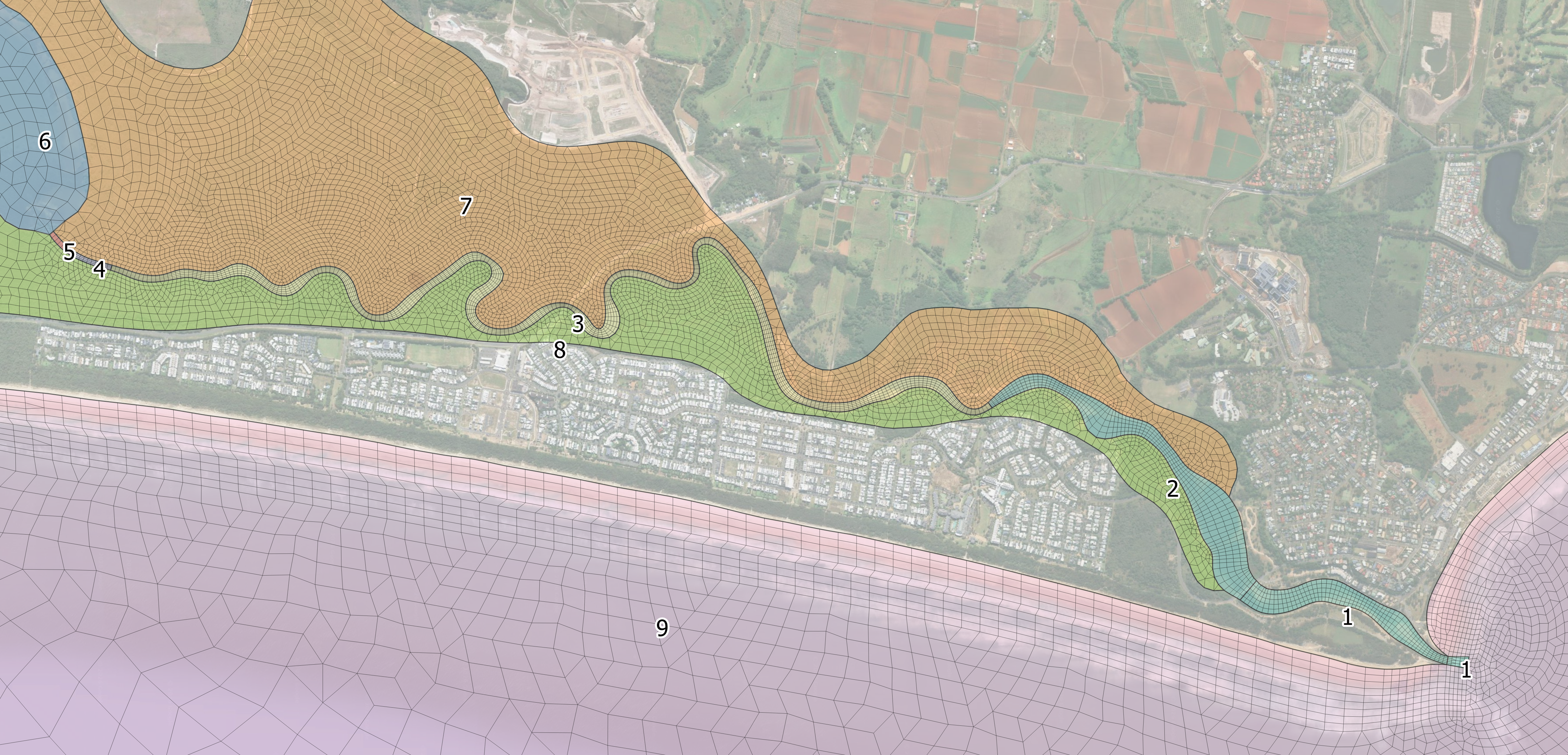
Figure 5.8: Material ID Spatial Definition
5.14.2.1 Material Properties
Material properties are specified within a material block. Material blocks begins with the
Example material blocks are provided as follows.
Bottom Roughness
This example shows a global bottom roughness that is modified locally by three materials.
This example shows a global bottom roughness that is locally modified within materials 3 and 4 using the same material block.
Horizontal Eddy Viscosity
This example shows material specific updates of eddy viscosity coefficients and limits.
Bed Elevation Limits
This example shows how bathymetry can be locally updated using a material block. Any bathymetry above -10 mRL is set to -10 mRL. The value -99999. is used to define a lower limit that will never be reached in practice. This means elevations below -10 mRL are not modified. Specifying -99999. is therefore equivalent to applying no truncation to bathymetry below -10 mRL.
Material Block With Multiple Properties
This example shows multiple bed properties being updated within a single material block.
5.14.3 Spatially Constant
The
5.14.4 Spatially Varying
GIS polygon layers can be used to set a the material ID for any cell centroids located within the polygon’s extent using the
During model initialisation (Section 5.2), template layers prefixed with ‘2d_mat_’ are generated for use in defining materials. ‘2d_mat_’ layers require the assignment of a single ‘MATERIAL’ attribute as shown in Table 5.27.
| Attribute Name | Description | Type |
|---|---|---|
| Material | Cell Material ID | Integer |