5.13 Bathymetry
5.13.1 Command Status
Conditional
Static bathymetry commands are optional if using an unstructured computational mesh.
Static bathymetry commands are required if using a structured computational mesh.
Time varying bathymetry commands are optional for either computational mesh type.
5.13.2 Description
Supported bathymetry model implementations are summarised in Table 5.22, with links to the relevant implementation sections below.
| Model Implementation | Description |
|---|---|
| Static | Static bathymetry assignment and layering approaches. This is bathymetry that does not change as a function of time during a simulation. |
| Time Varying | Time varying bathymetry implementation. Can be used to model levee breaches, rudiemtary scour or earthworks. |
5.13.3 Static Bathymetry
TUFLOW FV supports the assignment of static model bathymetry using a range of input formats, including unstructured mesh files (.2dm), Triangulated Irregular Networks (TINs), Digital Elevation Models (DEMs) and GIS vector layers. These datasets are used to define elevations across the model domain, enforce bathymetric breaklines and assign elevation values to specified spatial regions.
The workflow used to apply bathymetry depends on the mesh type. For structured meshes (Section 5.12.4), at least one static bathymetry command is required to define bed elevations. For unstructured meshes (Section 5.12.3) bathymetry is initially provided through the .2dm mesh file. This base .2dm bathymetry can then be optionally updated or replaced using the static bathymetry commands described in the following sections.
When using unstructured meshes it is generally preferable to disregard the bathymetry stored within the .2dm file and instead define bathymetry directly within the TUFLOW FV control file using external datasets. The reasons for this are as follows.
- The .2dm file contains both the mesh topology and a vertex based bathymetry dataset. Because the bathymetry is stored at mesh vertices it is inherently dependent on the mesh geometry. Any modification to the mesh topology requires the bathymetry to be regenerated
- During model initialisation, TUFLOW FV averages vertex elevations from the .2dm file to cell centred bathymetry values. This can lead to smoothing of narrow channels, banks, levees or other small scale features. For applications with relatively uniform bed levels, such as large lakes or offshore domains, this behaviour may be acceptable and the user can use the .2dm alone to define the bathymetry. For applications requiring accurate representation of fine bathymetric detail it is recommended to use bathymetric update commands
The recommended workflow to apply model bathymetry is as follows.
- The unstructured mesh is read from the .2dm file. The associated bathymetry is loaded by default during this step
- The initial bathymetry from Step 1 is disregarded by applying a global default bathymetry value (Section 5.13.3.2)
- Detailed bathymetric data are assigned using spatially varying datasets such as DEMs (Section 5.13.3.3) or TINs (Section 5.13.3.4). These commands interpolate elevations directly to cell centres and are mesh independent
- The base bathymetry established in the previous step can be locally modified to represent hydraulic controls or design features. For example using breaklines to define channel thalwegs, embankment crests, levees or other linear structures (Section 5.13.3.5) or to incorporate proposed earthworks, cut and fill operations
The static bathymetry command implementations listed in Table 5.23 are described in the sub sections that follow.
| Command | Description |
|---|---|
| Set Zpts | Optional - Sets all elevations in the domain to a user specified value (Section 5.13.3.2). |
| Read GRID Zpts | Optional - Updates cell centre elevations via a Digital Elevation Model (DEM) file (Section 5.13.3.3). |
| Read TIN Zpts | Optional - Updates selected cell centre elevations via a Triangulated Irregular Network (TIN) file (Section 5.13.3.4). |
| Read GIS Z Line | Optional - Reads GIS files that can contain polylines, points and/or polygons. Points and polylines are treated as breaklines in the model’s bathymetry (Section 5.13.3.5). The breakline can vary in height along its length (i.e. a 3D breakline). Polygon features set a user-specified z elevation that updates any cell centroids located within the polygon extent (Section 5.13.3.6). |
| Cell Elevation File | Optional - CSV file that updates cell centre elevations. Can be assigned using (ID, Z) or (X,Y,Z) coordinates (Section 5.13.3.7). |
| Global Bed Elevation Limits | Optional - Sets a spatially constant lower limit (zbmin) and upper limit (zbmax) to the model bathymetry. Model elevations below zbmin will be set to zbmin and likewise model elevations will be set to zbmax. This command is executed after all other bathymetry commands and will overwrite any preceeding bathymetry below or above the zbmin or zbmax values (Section 5.13.3.8). |
5.13.3.1 Static Bathymetry Layering
Static bathymetry commands can be applied individually or in combination, with TUFLOW FV input data layering determining the final bathymetric surface. This section provides an example of command layering for a proposed port upgrade where the model bathymetry is constructed using a series of topographic and bathymetric layers (see Figure 5.5).
- A default land elevation value of 10 m is set. As this is a coastal project, this value is well above the highest water level expected during the analysis. This default is set to ensure any missing data values in the GIS are filled in and can be easily identified.
- A TIN of bathymetric sounding data is used to define the existing ocean bathymetry, pre development.
- LiDAR derived survey is used to define the ‘base’ bathymetry for overland areas, pre development.
- The design TIN earthworks of the proposed port development are ‘stamped’ onto the existing ‘base’ bathymetry.
- Use a combination of polyline and point breakline layers to enforce the low chord of an approach channel within the proposed port development extent

Figure 5.5: Bathymetry Layering For Proposed Port Design
The corresponding TUFLOW FV command syntax is provided below.
The final bathymetry used by the simulation can be reviewed within the _mesh_check_R file if
5.13.3.2 Spatially Constant
A spatially constant single elevation can be set for the model domain using the
5.13.3.3 Direct Reading Of DEM Grids
The
5.13.3.4 Direct Reading Of TINs
Bathymetry can be assigned using TINs through the
5.13.3.5 Breakline Layers
The
Figure 5.6 shows an example using breaklines layers to enforce the bathymetry of a design bund. In the left pane a breakline polyline (black dash) has been digitised with elevation points (red circles) snapped to the start, middle and end polyline vertices with elevations -0.2, 1.0 and 0.5 m respectively. During model start up cell elevations are linearly interpolated along the polyline resulting in the cell centre elevation updates indicated by the pink triangles with red labels in the right image.
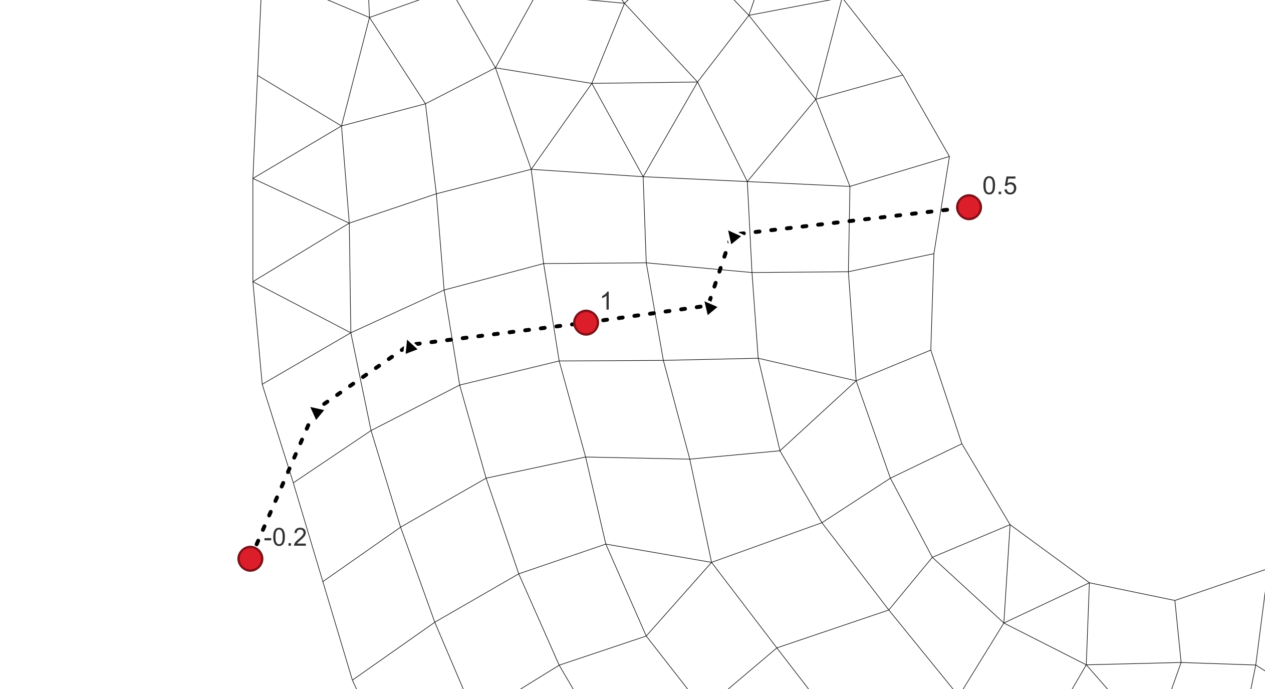
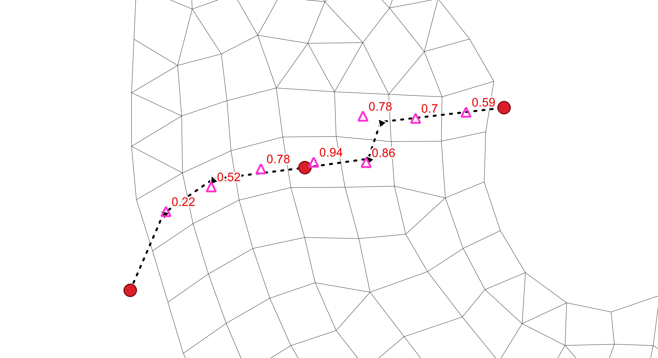
Figure 5.6: Breakline Definition Using Combination Of Polyline And Point GIS Layers
The template GIS layers required to define breaklines, prefixed with ‘2d_zln_’ are generated during model initialisation (Section 5.2). Multiple geometry types are supported and are indicated by the following suffixes:
_P for point features (e.g., 2d_zln_M03_002_P.shp)
_L for line features (e.g., 2d_zln_M03_002_L.shp)
‘2d_zln_’ layers require the assignment of a single ‘Elevation’ attribute as shown in Table 5.24.
| Attribute Name(s) | Description | Type |
|---|---|---|
| Elevation | Elevation of the feature relative to the model’s vertical datum. | Float |
When specifying
Multiple point files may be included but must not appear as the first entry in the list.
If using MapInfo .mif files, point and polyline geometries can be contained in a single .mif file if preferred.
Modified cell centre elevations are output to the 2d_zln_zpt_check layer if
5.13.3.6 Polygon Layers
GIS polygon layers can be used to set a spatially constant elevation for any cell centroids located within a polygon’s extent using the
The template GIS layers required to define elevation polygons, prefixed with ‘2d_zln_’ are generated during model initialisation (Section 5.2). For example:
- _R for polygon features (e.g., 2d_zln_Reclaimation_001_R.shp)
‘2d_zln_’ layers require the assignment of a single ‘Elevation’ attribute (see Table 5.24). An example syntax block is provided as follows.
A polygon (blue hatching in Figure 5.7) can be used to enforce the infill area associated with a proposed development. Cell centre values updated by the polygon can be visualised in GIS using the 2d_zln_zpt_check layer (see 5.18.11). The pink triangles indicate that bathymetry has been raised to 2 mRL. The symbology is the default styling applied using the TUFLOW Viewer Plugin for QGIS for check file layers.
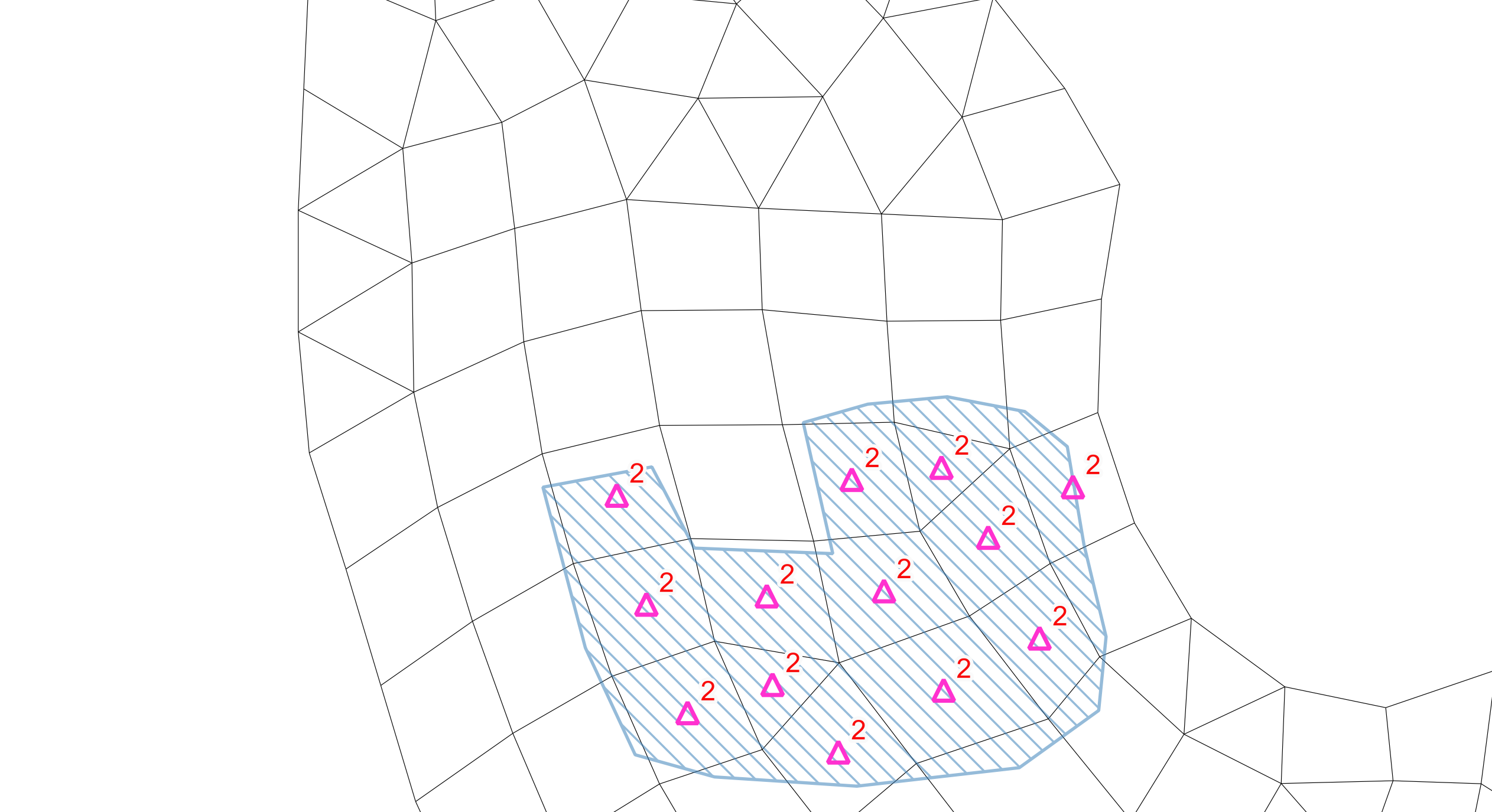
Figure 5.7: Filling Of Spoil Ground Modelled Using GIS Polygon
5.13.3.7 Preprocessed Cell Elevations
This method can be used in preference to the commands mentioned above if model startup times are prohibitively slow. Unlike other bathymetric assignment methods, cell ID referencing does not require interpolation enabling near instantaneous bathymetry assignment during model start up. However, this approach is mesh specific and requires preprocessing prior to running a TUFLOW FV simulation. If the mesh is modified, a new cell elevation file must be generated. Due to its dependence on the mesh structure, this method is recommended only if minimising model initialisation time is a priority.
The
Example subset of an input files using Cell_ID referencing.
OC_001_CC_Inspect_ID.csv - Total file size 22350 cells
ID, Z
1, -5.2
2, -8.3
..., ...
..., ...
22350, 3.3
Example subset of an input files using Coordinate referencing.
OC_001_CC_Inspect_XYZ.csv - Total file size 22350 cells
X, Y, Z
156.01842, -10.01357, -5.2
156.04195, -10.02864, -8.3
...,...,...
...,...,...
156.23608, -10.19135, 3.3
5.13.3.8 Bed Elevation Limits
The
Global bed elevation limit values can be overridden locally through use of material specific values (Section 5.14).
5.13.4 Time Varying Bathymetry
TUFLOW FV supports the specification of bathymetry that changes during the simulation using a set of time varying structure commands. These allow localised adjustments to bed elevation based on a prescribed time series, model sampled parameters (e.g. flow or level) or a combination of digital elevation model (DEM) surfaces and control rules. Common applications include the representation of levee breaches, sandbar migration or event driven scouring and deposition.
Time varying bathymetry is configured using TUFLOW FV’s hydraulic structure block functionality and thus is not repeated here (see Section 5.17.10).