5.12 Computational Mesh
5.12.2 Description
The computational mesh defines the horizontal spatial discretisation of the model domain and forms the geometric basis for all calculations in TUFLOW FV. Supported computational mesh model implementations are summarised in Table 5.20, with links to the relevant implementation sections below. The required commands for these implementations are summarised in Table 5.21. The following two mesh types are supported and the user is required to select one method or the other.
| Model Implementation | Description |
|---|---|
| Unstructured | Unstructured mesh implementation. |
| Structured | Structured mesh implementation. |
| Command | Description |
|---|---|
| Geometry 2D | Conditional - Required if using an unstructured computatoinal mesh. Reads the mesh topology from a .2dm unstructured mesh file. This mesh may contain triangles, quadrilaterals, or a combination of these geometries. The mesh may also contain bathymetry and material information. Only one Geometry 2d command and mesh should be used per simulation. |
| Grid Origin | Conditional - Required if using a structured mesh. X and Y coordinate of the grid origin. |
| Cell Size | Conditional - Required if using a structured mesh. The model cell size which can be independent in the X and Y directions. |
| Grid Size | Conditional - Required if using a structured mesh. The length of the X and Y grid axis. |
| Grid Rotation | Optional - Structured grid rotation angle. |
5.12.3 Unstructured Mesh
This is the usual mesh type used for TUFLOW FV modelling. TUFLOW FV supports unstructured meshes generated in the Aquaveo SMS .2dm file format. Unstructured meshes (also commonly referred to as flexible meshes) are typically used to represent complex geometries such as estuaries, rivers and coastal systems such as the mesh shown in Figure 5.2.
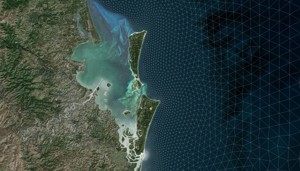
Figure 5.2: Moreton Bay Unstructured Mesh (Constructed Using Aquaveo SMS)
Detailed instructions on how to generate unstructured meshes are provided in TUFLOW FV’s Tutorial Modules. The tutorials range in complexity, and provide general guidance on meshing with links to educational meshing resources. It is strongly recommended that these tutorials be reviewed.
Unstructured meshes are read using the
5.12.4 Structured Mesh
Structured rectangular meshes, with or without rotation, are defined using the set of commands listed in Table 5.21. These meshes are useful for doing direct comparisons with other regular grid models or laboratory tests.
The
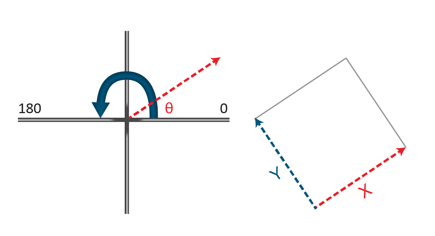
Figure 5.3: Regular Mesh Rotation Convention
Structured Mesh
The below example shows the development of a 20 m resolution cartesian model. The resultant mesh is shown in Figure 5.4
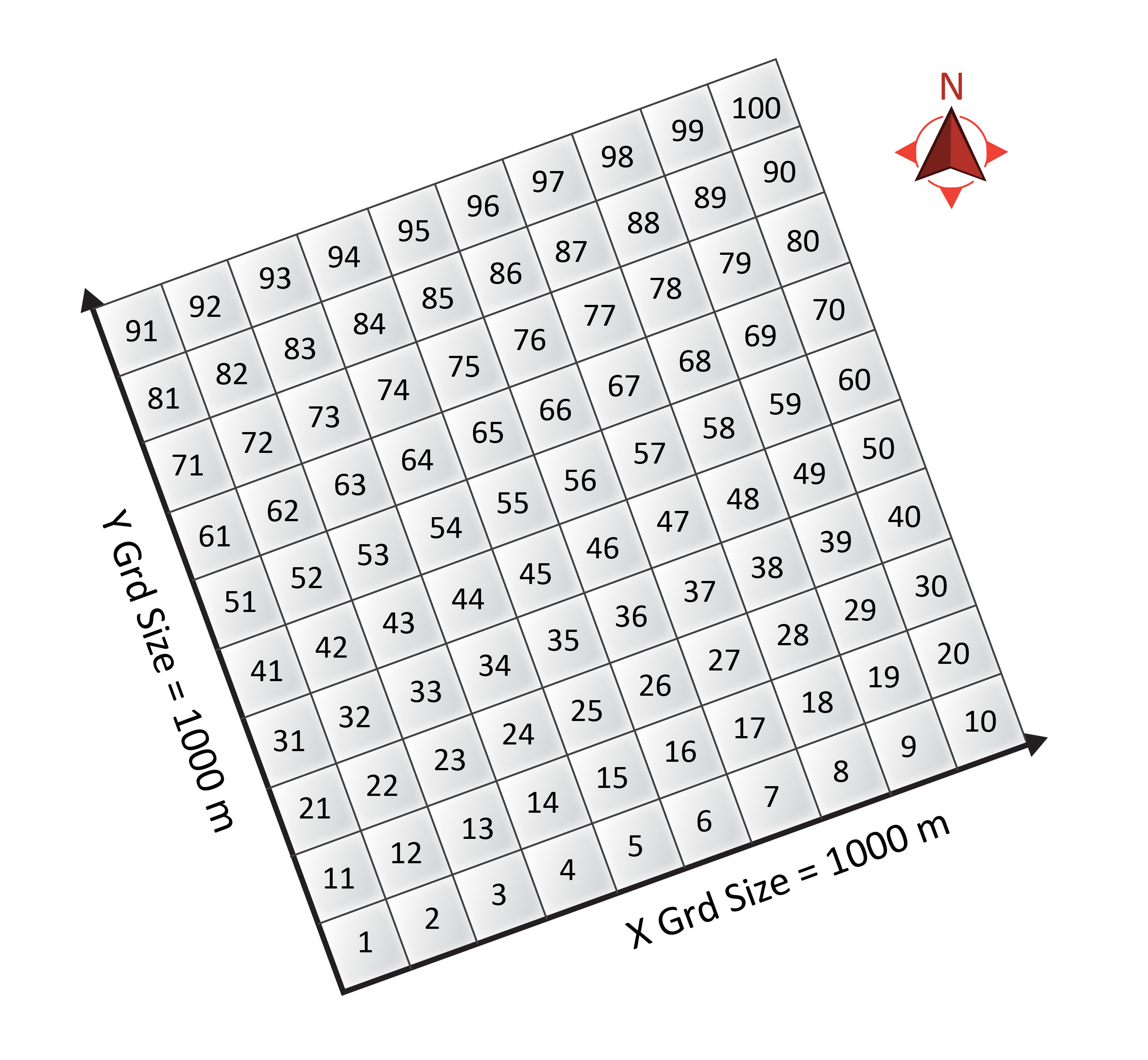
Figure 5.4: Example Regular Mesh - Cell IDs are presented at each cell centre