Appendix F TRFC Commands
The TUFLOW Rainfall Control File (.trfc) contains commands used to generate rainfall grids based on point rainfall gauges, it is read into the .tcf using the Rainfall Control File command. For more information on the .trfc see Section 4.2.11. Generating and using rainfall grids is discussed in Section 8.5.3.6. The TUFLOW Wiki also includes some useful discussion on this subject. The available TRFC commands are listed below and are detailed in Table F.1.
IDW Exponent
IDW Maximum Distance
IDW Maximum Points
Maximum Hyetograph Points
Maximum RF Locations
Read GIS RF Point
Read GIS RF Polygons
Read GIS RF Triangles
RF Grid Cell Size
RF Grid Format
RF Grid Origin
RF Grid Size (N,M)
RF Grid Size (X,Y)
RF Interpolation Method
| Command | Solver | Description |
|---|---|---|
|
|
Classic and HPC |
If using the |
|
|
Classic and HPC |
If using the |
|
|
Classic and HPC |
If using the |
|
|
Classic and HPC | Controls the temporary memory allocated for reading / storing the rainfall data. If more the 1,000 points occur in the rainfall hyetograph, this can be increased. Can also be reduced to decrease temporary memory allocation. Refer to Section 8.5.3.6 for more details. |
|
|
Classic and HPC | Controls the temporary memory allocated for reading / storing the rainfall data. If more the 1,000 point rainfall locations are used, this can be increased. Can also be reduced to decrease temporary memory allocation. Refer to Section 8.5.3.6 for more details. |
|
|
Classic and HPC | Read the point rainfall locations in the 2d_rf file format. For each point the attributes are Name, f1 and f2 factors. If the rainfall factors f1 and/or f2 are zero (or less than zero), these are changed to 1 and WARNING 2618 is issued. Refer to Section 8.5.3.6 for more details. |
|
|
Classic and HPC | The GIS layer contains a series of polygons or regions in the 2d_rf format. These polygons can either have the rainfall boundary Name (and f1 and f2 factors) specified on the polygon objects, or if these attributes are blank TUFLOW looks for rainfall points (specified with the Read GIS RF Points) that fall within the polygons. If the Name attribute in the polygon layer is blank and no points fall within the polygon an ERROR 2619 occurs. Refer to Section 8.5.3.6 for more details. |
|
|
Classic and HPC |
Reads in a GIS layer containing the triangulation of the rainfall points. The GIS objects should be polygons or regions with three vertices, with each vertex snapped to a rainfall point location as specified by Read GIS RF Points. The layer is typically produced by other software specialising in the interpolation of rainfall, but can be manually created when only a small number of rainfall locations exist. The attributes of the GIS layer are not used. For each grid cell in the rainfall output grids, the rainfall depth is based on the planar (linear) interpolation of the three rainfall depths at the vertices of the bounding triangle. An example of a triangulation polygon layer (red) connecting the rainfall point locations (blue) is shown below. Refer to Section 8.5.3.6 for more details. 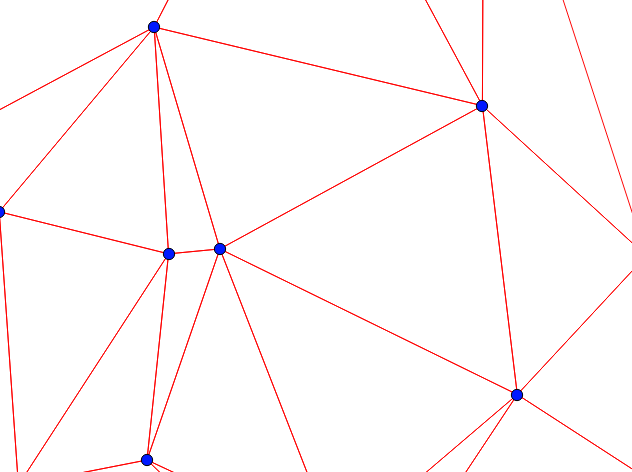
|
|
|
Classic and HPC | Sets the cell size for the generated rainfall grids. If omitted, a value 10 times the 2D domain cell size is used. Typically the rainfall can be satisfactorily represented on a much coarser resolution than that required for the hydraulic calculations, therefore, using high resolution rainfall grids is not required and unnecessarily consumes memory and disk space, and may slow down the simulation. Refer to Section 8.5.3.6 for more details. |
|
|
Classic and HPC |
This mandatory command sets the output grid format. Options are TIF (GeoTIFF - extension .tif) , FLT (ESRI binary grid – extension .flt), ASC (ESRI asc grid – extension .asc), or NC (NetCDF extension .nc). The rainfall grids are output to a separate folder (RFG\ \(\langle\) rainfall_grid \(\rangle\)) in the location of the .trfc file. If the .trfc file is in the bc_dbase\ folder, a new folder “bc_dbase\” is created containing the output grids. The output formats from the rainfall interpolation are compatible with the formats used by the .tcf Read Grid RF, therefore, once the rainfall grids have been generated this command can be used to apply the rainfall, rather than regenerate the rainfall grids using the .trfc file (should the .trfc input files remain unchanged). NC: If NetCDF output is specified a single output file (.nc) containing all timesteps in a single file is created. This is given the simulation name: TUFLOW_dbase\simulation_name \(\rangle\).nc ensuring that the dataset is not accidentally overwritten as the simulation is running. There is no limit to the number of rainfall timesteps that are included in the NetCDF format. A total rainfall depth is also output, however, this is not used by TUFLOW during the simulation, and it can be used for checking purposes. For more information see TUFLOW NetCDF Rainfall Format Wiki Page. TIF, FLT and ASC: A series of grids are written (one
for each hyetograph timestep) in the specified formats. Due to the
large number of grids that may be written, these are separated into a
sub-folder under the RFG\ folder, for example: An index file containing a list of the times and rainfall grid filenames
is written in .csv file format in the same folder, for example: |
|
|
Classic and HPC | Sets the origin for the output rainfall grid. If this command is omitted the rainfall grid origin is based on the origin of the TUFLOW 2D domain(s). Refer to Section 8.5.3.6 for more details. |
|
|
Classic and HPC | Sets the size of the output rainfall grids. Similar to the .tgc Grid Size (N,M) command. If omitted the rainfall grid size is based on the dimensions in the TUFLOW 2D domain(s). Refer to Section 8.5.3.6 for more details. |
|
|
Classic and HPC | Sets the size of the output rainfall grids. Similar to the .tgc Grid Size (X,Y) command. If omitted the rainfall grid size is based on the dimensions in the TUFLOW 2D domain(s). Refer to Section 8.5.3.6 for more details. |
|
|
Classic and HPC |
Sets the interpolation approach between rainfall locations. This command must be specified with one of the options as described below. IDW: An inverse distance weighting approach is used to calculate the rainfall depth based on the distance to the surrounding rainfall points (specified by Read GIS RF Points).
The exponent (p) can be changed from its default value of 2 using IDW Exponent. Other commands that affect the IDW interpolation are IDW Maximum Distance and IDW Maximum Points. POLYGON: A series of GIS polygons are specified and the rainfall for each polygon comes from the point rainfall. This can be used to apply distributions such as Thiessen polygons generated from other software. The regions or polygons are read in the 2d_rf format, and can either have the rainfall boundary Name (and F1 and F2 factors) specified via the polygon attributes, or if the attributes are blank TUFLOW will look for rainfall points (specified by Read GIS RF Points) that fall within the polygons. If the Name attribute in the polygon layer is blank and no points fall within the polygon an ERROR 2619 occurs. This method is similar to using a series of rainfall polygons read in via the .tbc Read GIS RF command. By pre-processing using a .trfc file, however significant more memory efficiency occurs, particularly if a large number of rainfall boundaries is used. TIN: A TIN (Triangulated Irregular Network) is specified via Read GIS RF Triangles which connects the rainfall point locations. |

