Section 4 Control Files and Input Layers
4.1 Introduction
This chapter discusses TUFLOW model inputs, which include the TUFLOW Control Files (text-based, easy to script, input files) and GIS layers (.shp, .gpkg or .mif formatted files). The different control files will be discussed along with how different objects within the GIS layers are treated by TUFLOW.
4.2 Control Files
The TUFLOW Control files are text files containing a series of commands (instructions) that control how a model is constructed and how a simulation proceeds. They are easily scripted and interpreted, typically short in length, and very powerful for enabling efficient workflows.
This overview chapter discusses:
- Rules and notation in regards to control files (Section 4.2.1),
- Absolute and relative file paths (Section 4.2.2),
- The available units (e.g. Metric or Imperial) (Section 4.2.3), and
- The control files (Section 4.2.4 to Section 4.2.16).
Table 4.1 lists the available control files, provides a brief description and a link to the respective section of this Chapter that discusses the individual control file.
| Control File | Description | Section |
|---|---|---|
| TCF | The TUFLOW Control File (.tcf) file sets simulation parameters and directs input from other data sources. It is the top of the tree, with all input files accessed via the .tcf file or files referred to from the .tcf file. Each TUFLOW simulation must have a .tcf file. | Section 4.2.4 |
| ECF | The ESTRY Control File (.ecf) includes all of the 1D files and commands. 1D commands can also be embedded into the .tcf file should the modeller prefer. | Section 4.2.5 |
| TBC | The TUFLOW BoundaryControl File (.tbc) includes commands related to internal and external boundaries and linking of 1D/2D. | Section 4.2.6 |
| TGC | The TUFLOW GeometryControl File (.tgc) includes commands and geometric / topographic data inputs to build the 2D domain. | Section 4.2.7 |
| QCF | The Quadtree Control File (.qcf) includes the commands required to build a quadtree mesh. | Section 4.2.8 |
| TEF | The TUFLOW Event File (.tef) includes a database of .tcf and/or .ecf commands related to specific events. | Section 4.2.9 |
| TOC | The TUFLOW Operational Control File (.toc) includes operating rules that can be applied to hydraulic structures, pumps and other controllable devices modelled as 1D elements. | Section 4.2.10 |
| TRFC | The TUFLOW Rainfall Control File (.trfc) includes commands to generate rainfall grids based on point rainfall gauges. | Section 4.2.11 |
| TESF | The TUFLOW External Stress File (.tesf) includes commands to define time varying global or spatially varying external forces such as wind or wave radiation stresses. | Section 4.2.12 |
| ADCF | The Advection Dispersion Control File (.adcf) includes the commands required for AD model execution. | Section 4.2.13 |
| TSCF | The TUFLOW SWMM Control File contains the relevant commands needed to manage the SWMM simulation. | Section 4.2.14 |
| Read File | A TUFLOW Read File is a file included inside another file. Any file extension be used, with .trd traditionally used for 2D commands and .erd for 1D. Read files are useful for commands that are common to multiple simulations or for commands that are rarely or never changed and can be placed into another file to reduce the size of the parent file. Up to 9 levels of read files can be nested. | Section 4.2.15 |
| Override File | Override Files allow the user to apply .tcf commands after TUFLOW has finished processing the commands which are referenced within the .tcf file. | Section 4.2.16 |
4.2.1 Rules and Notation
Control files, such as the TUFLOW Control File (TCF), TUFLOW Boundary Control (TBC) and TUFLOW Geometry Control (TGC), are command or keyword driven text or script files. The commands are entered free form, based on the rules described below. Comments may be entered at any line or after a command. The commands are listed in Appendix A to Appendix I.
Note: TUFLOW control files and commands are NOT case sensitive.
An example of a command is:
This command sets the simulation start time to 10 hours. The text to the right of the “!” is treated as a comment and not used by TUFLOW when interpreting the line.
Automatic colour coding (as shown in the above example) of files for easy interpretation is available, with download links and installation instructions, for the following text editors: Notepad++, UltraEdit and TextPad.
Commands can be repeated as often as needed. This offers significant flexibility and effectiveness when modelling, particularly in building 1D and 2D model topography. Note that a repeat occurrence of a command may override the effect of previous occurrence(s) of the same command.
The style of input is flexible bar a few rules. The rules are:
- A few characters are reserved for special purposes as described in Table 4.2;
- Command syntax is not case sensitive;
- Only one command can occur on a single line; and
- A few commands rely on another command being previously specified. These are documented where appropriate.
Additional text can be placed before and/or after a command. For example, a line containing the command Start Time to set the start time of a simulation to 10 hours can be written as:
The (h) text is not a requirement but is useful to indicate that the units are hours. Alternatively, the following would also be acceptable, noting the use of the comment delimiter “!”:
Blank lines are ignored. Spaces or indentations can occur at the start of the line. This is recommended when using the logic control, as outlined in Section 13.3. The second line in the following example is not required to be indented, however, it is strongly recommended to facilitate easy interpretation:
The notation used to document commands and valid parameter values in Appendix A to Appendix I are presented in Table 4.3.
| Reserved Character(s) | Description |
|---|---|
| “#” or “!” | A “#” or “!” causes the rest of the line from that point on to be ignored. Useful for “commenting-out” unwanted commands, and for all that modelling documentation. |
| == |
A “==” following a command indicates the start of the parameter(s) for the command. Where there is more than one parameter, the parameter values are read as free-field formatted, i.e. are space or comma delimited. When processing command line syntax within the control files (.tcf, .tgc, .ecf etc.), if a “==” is not present in the command line syntax TUFLOW will produce an ERROR 0060. For example “ |
| Documentation Notation | Description |
|---|---|
| < … > | Greater than and less than symbols are used to indicate a variable parameter. For example, the commonly used <file> example is described below. |
| <file> | A filename (can include an absolute or relative path, or a UNC path). See Section 4.2.2 for a more detailed description. |
| [ {Op1} | Op2 ] |
The square brackets “[” and “]” surround parameter options. The “|” symbol separates the options. The “{” and “}” brackets indicate the default option. This option is applied if the command is not used. For example, the options for the Maximums and Minimums command are: |
| spaces |
Spaces can occur in commands and parameter options. If a space occurs in a command, it is only one (1) space, not two or more spaces in succession. Spaces can occur in file and path names; however, third party software may not allow this and as such is not recommended. If using spaces in filenames, batch files will require that the filename is enclosed in quotes. |
4.2.2 File Paths
TUFLOW control files reference additional files, for example GIS files. The three methods that can be used are absolute file path, relative file path and UNC file path referencing. A model can use any or all these methods. However, relative file paths are typically preferred.
Note: Depending on the operating system, file paths may be case sensitive.
Take an example of reading a GIS layer containing initial water levels, the command is
- Absolute file path:
Read GIS IWL == L:\2d_IWL_001_R.shp
- Relative file path:
Read GIS IWL == ..\2d_IWL_001_R.shp
- UNC file path:
Read GIS IWL == \server1\2d_IWL_001_R.shp
For the relative file path, the path is relative to the file that is referring to it. In the case above, if the command occurred in the .tcf file, which is in the TUFLOW\runs\ folder, the ..\ indicates to go up one level (from TUFLOW\runs\ to TUFLOW\ the model\ navigates into the TUFLOW\model\ folder, gis\ navigates from TUFLOW\model\ into TUFLOW\model\gis\). To go up more than one level simply use ..\ multiple times (e.g. ..\..\ would navigate up two folders). If the file sits under the same folder, then the filename can be specified. In the below example the Model_Events.tef would need to sit in the same location as the .tcf.
The paths are relative to the current control file, a command in the geometry control file (TUFLOW\model\) would be relative to the .tgc location, not the .tcf location.
Using relative file paths has the advantage that the model can be moved or provided to another user and the control files do not need to be updated, if the model uses an absolute or UNC file path, all references will need to be updated if the model is moved.
Some large files may still use an absolute or UNC file path particularly where large datasets are shared across models. This avoids the need to copy the dataset into multiple projects. An example is:
If using LINUX at any point during the modelling tasks or pre/post processing, it is recommended to set
4.2.3 Units
The default unit settings for all inputs in a TUFLOW model are metric, however, it is possible to create models using US Customary units (also known as Imperial or English units) by specifying the .tcf command
This manual uses the metric term for documentation purposes. If your model uses US Customary Units any user defined values must also be specified in US Customary units. The metric unit and the equivalent US Customary unit are listed in Table 4.4, unless otherwise stated within this Manual. Model units can be checked by searching for the relevant parameter in the .tlf file (refer to Section 14.4).
Output units are listed in Table 11.4.
| Metric | US Customary |
|---|---|
| m | ft |
| mm | inches |
| km2 | miles2 |
| kg | pound |
4.2.4 TCF
The TUFLOW Control File (.tcf) file sets simulation parameters and directs input from other data sources. It is the top of the tree, with all input files accessed via the .tcf file or files referred to from the .tcf file. Each TUFLOW simulation must have a .tcf file. An example of a simple .tcf file is shown in Figure 4.1.
The .tcf file must reference the following items as a minimum requirement (TUFLOW won’t run without them):
- Geometry Control File (Section 4.2.7)
- BC Control File (Section 4.2.6)
- Start Time
- End Time
- Map Output Interval
Recommended or most commonly used .tcf commands are:
- Read Materials File
- BC Database
- Solution Scheme
- ESTRY Control File (Section 4.2.5)
- Quadtree Control File (Section 4.2.8)
- SHP Projection/GPKG Projection/MI Projection
- Timestep
- Output Folder
- Map Output Data Types
- Time Series Output Interval
- Write Check Files and
- Write Empty GIS Files.
Commonly used or useful .tcf commands are: BC Event Name; BC Event Text; Event File, Read File, Cell Wet/Dry Depth; Instability Water Level; Read GIS FC; Read GIS IWL; Read GIS PO; Screen/Log Display Interval; Set IWL; Start Map Output; Start Time Series Output.
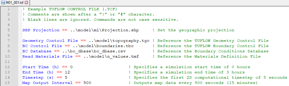
Figure 4.1: Example of a Simple TCF
Appendix A lists and describes .tcf commands and their parameters.
Note that it is possible to incorporate 1D (.ecf) commands into the .tcf file. 1D (.ecf) commands can be included in the .tcf file between Start 1D Domain and End 1D Domain block(s). For the .tef file, 1D (.ecf) commands must be prefixed by “1D”. Also note that ESTRY Control File command is recognised every time if specified more than once.
4.2.5 ECF
Commands specific to TUFLOW (ESTRY) 1D domains are detailed in Appendix B, and can be placed either in the .tcf file (or in a Read File), or in their own file traditionally called an .ecf file. 1D commands can be located:
- Within an .ecf file and referenced within the .tcf file using the command ESTRY Control File. The command ESTRY Control File Auto can be used to force the .ecf file to have the same name as the .tcf file.
- Placed within a 1D domain block in the .tcf using Start 1D Domain and End 1D Domain
commands.
- Placed anywhere in the .tcf file and preceded by “1D”, for example, 1D Manhole Default Type. “1D” must be the first two characters.
- Any combination of the above, however, it is strongly recommended in the interests of manageability that a logical approach be adopted (that agrees with your colleagues!).
The .ecf file method is typically used if the 1D domain is large and complex, whereas the 1D domain block or preceding “1D” may be used where the 1D/2D linked model requires only a few 1D commands or they are placed in another file and referenced using Read File.
The 1D commands set simulation parameters and directs input from other data sources for all 1D domains. An example of some 1D commands are shown in Figure 4.2.
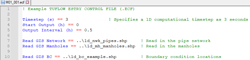
Figure 4.2: Example of a Simple ECF
Appendix B lists and describes the 1D commands and their parameters. Commands that are only relevant for 1D only models are indicated with a “1D Only” underneath the command in Appendix B.
Note: At present it is not an option to truly have a 1D only model. For 1D only models, a single 2D model, which can be made up of a single inactive 2D cell, is still required.
4.2.6 TBC
The .tbc file or TUFLOW Boundary Conditions Control File (TBC) contains information regarding the location and type of boundaries within the model. These include (but are not limited to) upstream and downstream boundaries as well as 1D/2D or 2D/2D links. The GIS layers read into the .tbc file reference the Boundary Condition (BC) Database (see Section 8.6). The BC Database associates the GIS layers with a boundary condition such as a hydrograph or a depth-discharge curve.
Only one .tbc file per 2D domain can be specified in the .tcf file using the BC Control File command. A .tbc file must be specified, if no external boundaries are to be applied a blank file may be specified. This is rarely done but can be used for models based only on initial water levels.
Appendix D lists and describes .tbc commands and their parameters.
4.2.7 TGC
2D domains are defined through a series of commands contained in TUFLOW Geometry Control (.tgc) files. The .tgc file contains, or accesses from other files, information on the size and orientation of the grid, grid cell codes (whether cells are active or inactive), bed/ground elevations, bed material type or flow resistance value, and optional data such as soil type.
A 2D domain is automatically generated as a grid of square cells. Each cell is given characteristics relating to the topography such as ground/bathymetry elevation, bed resistance value and initial water level, etc.
A .tgc file is specified in the .tcf file using Geometry Control File. For a TUFLOW Classic Multiple 2D Domain model, a separate .tgc file is required for each of the 2D domains, see Section 10.7.2.
Rather than contain all the 2D grid information in one file, the .tgc file is a series of commands that builds the model. The commands are applied in sequential order; therefore, it is possible to override previous information with new data to modify the model in selected areas. This is extremely useful where a base dataset exists, over which areas need to be modified to represent other scenarios such as a proposed development. This eliminates or minimises data duplication.
The commands can occur in any order (as long as it is a logical one).
If an unrecognisable command occurs, TUFLOW stops and displays the unrecognisable text.
Notes & Tips:
- Commands can be repeated any number of times.
- Commands are executed in the order they occur. If the data for a 2D cell or Zpt is supplied more than once, the last data that is read is used (i.e. the latter data for a cell overrides any previous data for that cell).
- Each data layer does not have to cover the entire model – only the 2D cells influenced by the objects in the layer (e.g. a 3D breakline) are affected.
- Use Write Check Files commands to cross-check and carry out quality control checks on the final 2D grid, elevations, material or land-use categories, etc.
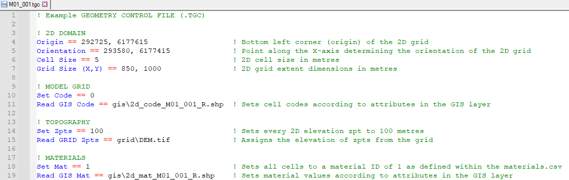
Figure 4.3: Example of a Simple TGC
Appendix C lists and describes .tgc commands and their parameters. An example of a .tgc file is shown in Figure 4.3.
4.2.8 QCF
For a quadtree grid, the Quadtree Control File (.qcf) is used to define the grid refinement areas and optionally the model location and extent, see Section7.4.1. A .qcf file is specified in the .tcf file using the Quadtree Control File command.
For a quadtree grid, only one .tgc file can be specified that covers all the 2D cell resolutions. The .qcf file primarily controls the nesting levels of different 2D cell resolutions, but may also control the overall grid orientation and location instead of the .tgc file. An example of setting up a model to use a quadtree grid is provided in TUFLOW Tutorial Module 7.
Appendix H lists and describes .qcf commands and their parameters.
4.2.9 TEF
The TUFLOW Events File (.tef) contains a database of .tcf and .ecf file commands for different events. A .tef file is specified in the .tcf file using the Event File command. Events are set up using a define event block, for example:
Event management is a powerful functionality that allows running multiple event combinations (e.g. magnitude, duration, temporal patterns, climate change) using a single set of control files rather than creating a new set of control files for every simulation. This makes the management of the model easier, ensures consistency between the simulations, and better quality control. An example of the number of .tcf and bc_database files required for a model with and without event management is shown in Figure 4.4.
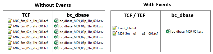
Figure 4.4: Reduction of Control Files using Event Management
Event management is detailed in Section 13.3.1. An example of setting up a model to use event management is provided in TUFLOW Tutorial Module 9.
4.2.10 TOC
The TUFLOW Operations Control (.toc) contains operating rules for structures. A .toc file is specified in the .ecf file using the Read Operating Controls File command, or in the .tcf file within a Start 1D Domain block. Operational Channels are detailed in Section 5.10. An example of its use is provided in TUFLOW Tutorial Module 10 Part 3.
Appendix E lists and describes .toc commands and their parameters.
4.2.11 TRFC
The TUFLOW Rainfall Control File (.trfc) contains commands used to generate rainfall grids based on point rainfall gauges. This approach generates a series of rainfall grids available to the user for display or checking. A .trfc file is specified in the .tcf using the Rainfall Control File command. An example of its use is provided in TUFLOW Tutorial Module 6 Part 3.
Appendix F lists and describes .trfc commands and their parameters.
4.2.12 TESF
The External Stress File (.tesf) allows the definition of time varying global or spatially varying external forcing such as wind or wave radiation stresses. A .tesf file is specified in the .tcf using the External Stress File command. External stress boundaries are discussed in Section 8.8.
Appendix G lists and describes .tesf commands and their parameters.
4.2.13 ADCF
The TUFLOW Advection Dispersion Control File contains commands related to the TUFLOW Advection Dispersion (AD) Module for simulating depth-averaged, constituent fate and transport. The .adcf is specified in the .tcf using the AD Control File command. The Advection Dispersion module is discussed in Chapter 9.
Appendix J lists and describes .adcf commands and their parameters.
4.2.14 TSCF
TUFLOW 2D domains can be dynamically linked to SWMM’s 1D solution scheme. The TUFLOW SWMM Control File (.tscf) contains the SWMM input commands. The .tscf file is specified in the .tcf using the SWMM Control File command. Section 10.4 provides information on linking to the 1D scheme, and examples are given in the TUFLOW SWMM Tutorials.
Appendix I lists and describes .tscf commands and their parameters.
4.2.15 Read File
The Read File command is extremely useful for placing commands that remain unchanged or are common for a group of simulations in another file (e.g. the SHP Projection command will be the same for all runs within the same study area). This reduces the size/clutter of .tcf files and allows easy global changes to a group of simulations to be made.
The file extensions most commonly used are .trd (2D commands), .erd (ESTRY 1D commands) and .rdf.
4.2.16 Override Files
These optional override files allow the user to apply .tcf commands after TUFLOW has finished processing the commands referenced within the .tcf file. This can be useful where you wish to change a parameter for all simulations that are started from a common folder. For example, you could turn off check files, or change the output drive.
Two override file types are possible, one which is computer specific and one which is processed by all computers. If either or both are present, they are processed after all the .tcf file commands have been processed so that the override commands prevail.
The first override file that TUFLOW checks for is named “_TUFLOW_Override.tcf”. If this file exists within the same folder as the .tcf file, .tcf commands that are listed within the “_TUFLOW_Override.tcf” file overwrite the commands in the .tcf file.
The second one TUFLOW looks for must be named “_TUFLOW_Override_<computer_name>.tcf”, where <computer_name> is the name of the computer running the simulation. If this file exists TUFLOW will process any commands within it after any commands from the “_TUFLOW_Override.tcf” file (if it exists). If you are unsure of your computer name, this is displayed in the computer’s properties or in a TUFLOW Log File (.tlf) that has been processed on that computer, this is typically at the top of the .tlf (line 6). For example:
With the computer name above the computer specific override file would be named “_TUFLOW_Override_COMP1234.tcf”.
An override file specific to a particular computer can be particularly useful where, for example, different output drives or results folders, are to be used for runs using different computers. This will allow you to run TUFLOW simulations on different computers without having to change the .tcf file.
For example, if a run is started on one machine that only has a C drive, output can be directed to the C drive just for that computer by using the command
Another example is if using the GPU solver and one machine only has a single GPU, while another has four GPUs. The command
Nearly all .tcf commands can be placed within the override files except for “Read GIS” and some other similar commands that involve processing of data layers. It is recommended that the override files are only used for global changes to settings, similar to the examples above.
4.3 Databases
Databases are organised collections of structured data in comma delimited (.csv) or text based formats that can be read into TUFLOW Control files. Table 4.1 lists the available databases, provides a brief description and a link to the respective section that discusses the specific database.
| Database | Description | Section |
|---|---|---|
| bc_dbase | The boundary condition (BC) database can be in either .csv (comma delimited) format, or HEC-DSS (see Section 8.6.5). It must contain a row with the pre-defined keywords ‘Name’ and ‘Source’, as listed in Table 8.12. Other keywords control how data is extracted from the source. | Section 8.6 |
| materials | The materials database can be in either a text based format (.tmf) or comma delimited format (.csv). It contains the Manning’s n value and other information for different materials (e.g. land-uses). The format of the materials .tmf file is described in Table 7.11. The format of the materials .csv file is described in Table 7.10. | Section 7.3.6.3 |
| pit_dbase | For pit channels specified as a Q Type, the flow through the pit is controlled by a depth-discharge curve defined within the Pit Inlet Database. The database file sources depth-discharge curves in other .csv files. The format of the Pit Inlet Database is described in Table 5.26. | Section 5.11.3 |
| soils | Soils infiltration is applied to the model by defining a soils (.tsoilf) file which is read into the .tcf using the command Read Soils File. An integer ID to each soil, define the infiltration method followed by the soil parameters as the remaining values. Table 7.13 presents the parameters of the .tsoilf file available for TUFLOW Classic, the additional options available for TUFLOW HPC are presented in Table 7.21. | Section 7.3.7.2 |
4.4 Input Layers
4.4.1 Input Formats
The main types of GIS Inputs are vectors, rasters and TINs. The following formats are supported as inputs in TUFLOW:
- GIS vector data layers: GeoPackage (.gpkg) (recommended), Shapefile (.shp) and MapInfo (.mif) (default) formats.
- GIS raster data layers: GeoTIFF (.tif) (recommended & default), GeoPackage (.gpkg), Float (.flt) and ASCII (.asc) formats. NetCDF formats are supported for some inputs such as time-varying rainfall grids.
- GIS TIN data layers: Land XML (.xml), 12d tin (.12da) formats (including super TINs) and SMS (.tin).
Most mainstream CAD/GIS platforms recognise these formats.
The format of input layers is solely controlled by the file extension. For example, for the vector formats, “.gpkg” for the GPKG format database (noting that no extension is used for a layer within a database), “.shp” for the SHP format and “.mif” for the MIF format. Prior to the 2023-03 release, if no file extension was specified TUFLOW assumed the input layer was in .mif format. To support the new GeoPackage format (the recommended vector format), TUFLOW will produce ERROR 0631 for inputs with no extension.
TUFLOW requires that all GIS layers imported or exported by TUFLOW must be in the same geographic projection. The model projection is initialised using the GPKG Projection, SHP Projection and MI Projection commands. Multiple input formats can be used (e.g. a mix of all format types within one model is allowed). If a model uses a mixture of format types as inputs, a projection command should be specified for each format.
The default output format for GIS check layers and GIS outputs depends on the Projection setting as mentioned above. If more than one Projection setting is specified, or to force the GIS output format, use the GIS Format command. The GeoPackage format is that recommended due to superior file/data management storage, data compression, and far greater viewing and querying speeds.
The default raster format is the GeoTIFF (.tif) format. Although a check is not done on the projection of .tif inputs, a projection can be assigned to .tif output rasters using the TIF Projection command.
4.4.2 GIS Commands
Commands containing “GIS” read and/or write a GIS vector layer. GIS commands read the geometry, attribute data, and projection data of the input layer. The available formats of input vector and raster layers are listed in Section 4.4.1. The geographic location of objects for GIS commands is important as the geographic position of the object controls the part of the TUFLOW model they affect.
When digitising objects, it is preferable that they do not snap to the 2D cell sides or corners as this may produce indeterminate effects.
4.4.2.1 GIS Attribute Interpretation
TUFLOW expects certain attributes, in a specific order for input layers. For example an initial water level layer (2d_iwl) layer only requires a single attribute (which is the initial water level value), whilst a 1d channel layer (1d_nwk) has a number of attributes including channel type, channel roughness, upstream and downstream elevation. The attributes required for each input layer are detailed in their respective sections throughout this manual. Any additional attributes appended to the layer will be ignored by TUFLOW (with the exception of the 1d_nwk layer as TUFLOW will treat it as a 1d_nwke layer).
The .tcf command Write Empty GIS Files can be used to automate the creation of template files with attribute structures that TUFLOW expects and with the recommended GIS data naming convention. They also can be automatically created using the TUFLOW Plugin Import Empty Tool.
A list of the TUFLOW template files is available on the TUFLOW Wiki.
The names of GIS attributes as documented or produced by Write Empty GIS Files may change from previous TUFLOW releases to reflect new features and changes. The name of the attribute is irrelevant as far as TUFLOW is concerned as TUFLOW only requires that attributes are in the correct order and of the correct type (i.e. Character, Float, Integer, etc.). In all TUFLOW layers, the attributes can be named as the modeller wishes, so older layers that do not have the same attribute names as documented in this manual will still work correctly.
4.4.2.2 GIS Object Interpretation
Table 4.6 and Table 4.7 outline the compatible GIS objects and how they are interpreted by TUFLOW.
Object snapping is often used to relate point data with line and region data, for example with the Read GIS Z Shape or Read GIS BC command. TUFLOW supports point, end and vertex snapping. It does not support edge snapping. Objects that are linked (for example a 2d_bc “SX” type region and 2d_bc “CN” type line layer), must be snapped and also read in to TUFLOW on the same command line separated by a vertical bar “|”. For example:
| Object Type | TUFLOW Interpretation |
|---|---|
| Point | Refers to the 2D cell that the point falls within or a 1D object such as a node or boundary location. Points snapped to the sides or corners of a 2D cell may give uncertain outcomes as to which cell the point refers to. |
| Line (straight line) | Variety of uses including defining a continuous line of 2D cells, 1D channels, to connect objects, alignment of a 3D breakline, linking 1D and 2D elements. |
|
Pline (line with one or more segments) |
As for Line above. |
| Region (polygon) |
For 2D cells either:
1D nodes within the region are selected. If the 1D node falls exactly on the region perimeter uncertain outcomes may occur. |
| Multiple (Combined) Objects | In later versions of TUFLOW, multiple point, line and region objects are generally accepted (ERROR or WARNING messages are given if not the case). |
| Object Type | TUFLOW Interpretation |
|---|---|
| Arc | Ignored (do not use). |
| Collections | Not supported. Collections are groups of objects of differing type. |
| Ellipse | Ignored (do not use). |
| none | These objects are ignored and most commonly occur when a line of attribute data is added that is not associated with an object. In MapInfo, this occurs when a line of data is added directly to a Browser Window (i.e. no object was digitised). |
| Roundrect (Rounded Rectangle) | Ignored (do not use). |
| Rect (Rectangle) | Ignored (do not use). |
| Text | Ignored. |
4.4.3 GeoPackage Commands
GeoPackage is a widely supported, open format, built upon an SQLite database (this is stored as a single file with the extension .gpkg). The benefits of GeoPackage compared to the MapInfo (MIF/MID) and ESRI/QGIS Shapefile formats include:
- More than one layer can be stored in a single file. For example, all model inputs can be stored in a single GeoPackage database.
- It supports spatial indexing, making it much faster to work with in GIS packages.
- Significantly faster write speed from TUFLOW compared to the Shapefile format.
For tips on using GeoPackages, see the GeoPackage Tips TUFLOW Wiki page. Additionally, the TUFLOW Tutorials are set up using the GeoPackage format and can be used as an introduction to using GeoPackages.
4.4.3.1 GPKG Input Commands
Since a GeoPackage database can have more than one layer, when reading data into TUFLOW, a GeoPackage file and table may both need to be specified. There are a variety of different options available. The following are possible:
To specify a table in a .gpkg directly use “>>”:
Read GIS Z Shape == gis\2d_zsh.gpkg >> 2d_zsh_L If a .gpkg file path is only specified, with no table reference, it will be assumed that the table name is the same as the .gpkg database name. For example, the following two commands are equivalent to one another:
Read GIS Z Shape == gis\2d_zsh_L.gpkg
Read GIS Z Shape == gis\2d_zsh_L.gpkg >> 2d_zsh_L To specify more than one table in a database in the same command line use “&&”. This is similar to “|” however there is no need to reference the database multiple times:
Read GIS Z Shape == gis\2d_zsh.gpkg >> 2d_zsh_L && 2d_zsh_P
“&&” can be used in conjunction with “|”:
Read GIS Z Shape == gis\2d_zsh_R.gpkg | gis\2d_zsh.gpkg >> 2d_zsh_L && 2d_zsh_P Use the command “USE ALL” with “>>” to tell TUFLOW to use all tables in the database:
Read GIS Z Shape == gis\2d_zsh.gpkg >> USE ALL Use the Spatial Database command to specify a database to use for subsequent table inputs. This command can be used multiple times in a control file to change the target .gpkg file. For example:
Spatial Database == gis\2d_EXG.gpkg
Read GIS Z Shape == 2d_zsh_R | 2d_zsh_L | 2d_zsh_P
Read GIS Mat == 2d_mat_R
Spatial Database == gis\2d_DEV.gpkg
Read GIS Mat == 2d_mat_R Spatial Database can be used in the .tcf, .ecf, .tbc, .tgc, .qcf, .tef. Commands are localised to their relevant control file with the exception of the .tcf which acts as a global command. If local spatial database are specified, they will take precedence over the global .tcf spatial database. The spatial database can be turned off or reverted to the .tcf database with the same command. Turning the spatial database off is a global command even when used in a control file other than the .tcf.
Spatial Database == OFF | TCF Prior to TUFLOW’s implementation of GeoPackage, if a file reference did not have an extension listed in the TUFLOW command syntax it was assumed the file was a MapInfo “mif” format. That rule no longer applies. If there is an open spatial database TUFLOW will not append “.mif” to the end of the table name.
4.4.3.2 GPKG Output Commands
The GIS outputs from TUFLOW can be set to GPKG by using the following command:
Outputs can be written into separate databases or grouped:
Grouped databases will group by output folder location. Separate databases will still group geometries together e.g., PLOT_P, PLOT_L, PLOT_R will be written to one database.
4.4.4 Grid Commands
Commands containing “Grid” read and/or write a GIS raster layer. The format is controlled by the file extension (e.g. .tif, .gpkg, .flt or .asc). The available formats of input raster layers are listed in Section 4.4.1.
For real (float) inputs the value is interpolated from the grid. For integer inputs (such as Code), the value applied is the integer value of the grid cell that the TUFLOW point falls within.
The Read Grid Zpts command permits a second argument to specify a GIS layer containing one or more polygons to clip the area of Zpts to be inspected. Elevations will only be assigned to Zpts lying inside polygons within the GIS layer. See Section 7.3.5.1 for more details.
4.4.5 TIN Commands
Commands containing “TIN” (triangulation file) read and/or write a TIN file. The format is controlled by the file extension (e.g. .tin, .xml or .12da). From the 2020-10-AB release, TUFLOW also supports super TINs in the .12da format. The same syntax is used for “TIN” layers as “GRID”.
TUFLOW can also be used to create a TIN (see Create TIN Zpts).
The Read TIN Zpts command permits a second argument, specifying a GIS layer containing one or more polygons to clip the area of Zpts to be inspected. Elevations will only be assigned to Zpts lying inside polygons within the GIS layer. See Section 7.3.5.1 for more details.
4.4.6 RowCol Commands (Legacy)
Commands containing “RowCol” or “MID” (e.g. Read RowCol Zpts) only read the attribute data file (i.e. .mid or .dbf file). This is a legacy feature and is not recommended for use. The row and column numbering in the TUFLOW model will change if the model cell size, orientation or origin change, this feature is therefore not supported when using quadtree grids or the GeoPackage format.
For details on this legacy feature see Section 4.9.2 of the 2018 TUFLOW Manual.
4.5 Layering Data
One of TUFLOW’s most powerful features is the ability to layer and prioritise data layers of the same data type. This means that TUFLOW constructs the model from the data layers with no need to copy or duplicate input data for the thousands of simulations that may ensue. Data layering has considerable benefits in terms of quality control and workflow efficiencies. Section 4.2.7 further details data layering.
4.6 XF Files
XF Files are a binary echo of selected input files automatically created by TUFLOW to vastly speed up the model initialisation process next time a simulation is carried out. If the original input data has a save date later than its corresponding XF file, the original data is read and the XF file re-created. If the XF file is newer, it is used in preference to the original data.
XF files are always written to a folder named “xf” underneath where the original data resides. If the “xf” folder or a XF file is deleted, the XF files will be recreated next time a simulation is started. The name of the XF file generated is that of the source file plus additional info. Two extensions are used: .xf4 and .xf8. .xf4 refers to iSP (single precision) runs and .xf8 to iDP (double precision) runs. It is not possible to mix these (i.e. to read an .xf4 single precision file into a double precision model).
To globally switch XF files off use
For the various commands that generate XF files (e.g. Read Grid Zpts, it is possible to refer directly to the .xf file instead of referring to the GIS layer, for example:
If different models utilise the same DEM(s), the DEM .xf file is reprocessed each time a different model is run. This can slow the model initialisation. To prevent this, the .tcf command XF Files Include in Filename adds unique text to the end of the .xf filenames for each model.
For example, if two models use the same DEMs for setting Zpt values, use this command as per below.
In Model 1’s .tcf file:
In Model 2’s .tcf file:
If the same .tcf file is being used to run both models, use the scenario name as follows.
TUFLOW will add the ~s1~ value to the end of any .xf filenames (refer to Section 13.3.2 on the automatic setting of scenarios and events as variables). Thus, when ~s1~ changes from one simulation to the next, the .xf filenames are unique to that scenario and will not need reprocessing.
