3.1 Geolocation
Manually linking catchment and receiving water models can potentially be a time consuming and error prone process. When executed in configurations other than Pollutant Export (see Section 1.3), TUFLOW CATCH undertakes this task automatically via a process of geolocation, whereby TUFLOW HPC cells that spatially coincide with either TUFLOW FV nodestring inflows (user nominated, see Section 4.5.4) or TUFLOW FV mesh cells are identified. These TUFLOW HPC cells are called transfer cells. Once identified, these transfer cells track the local surface and groundwater flow volumes and constituent masses predicted by TUFLOW HPC, and each transfer cell’s outflows are converted into timeseries and exported into the comma delimited (.csv) format expected by TUFLOW FV as boundary conditions. It is noted that:
- Where the user has nominated a nodestring/s as transfer locations from TUFLOW HPC to TUFLOW FV, TUFLOW CATCH will write the corresponding TUFLOW FV boundary condition files as ‘Q’ types that include the transfer of momentum from TUFLOW HPC to TUFLOW FV. As such, these boundaries (and specifying the corresponding TUFLOW FV nodestrings) should be considered where channelised riverine inflows and the like are to be matched, i.e. where inflow momentum is important in controlling receiving water hydrodynamics
- Where TUFLOW CATCH automatically geolocates non-nodestring transfer locations from TUFLOW HPC to TUFLOW FV, TUFLOW CATCH will write the corresponding TUFLOW FV boundary condition files as ‘QC’ types that exclude the transfer of momentum from TUFLOW HPC to TUFLOW FV. As such, these boundaries should typify non-channelised ‘lateral’ inflows where momentum transfer is less important in controlling receiving water hydrodynamics
- Boundary data for TUFLOW FV is written with date (dd/mm/yyyy hh:mm:ss) format
- TUFLOW HPC cells that are located within the TUFLOW FV mesh but are not transfer cells (e.g. lie well within the TUFLOW FV model mesh) are designated as deactivated within TUFLOW HPC and are not included in simulation
This automated selection of linkage cells is sufficiently robust to handle relative differences in mesh/grid resolution between TUFLOW HPC and TUFLOW FV, including cases where the TUFLOW HPC model is higher resolution than the (local) TUFLOW FV model mesh, and vice-versa. Some typical cases are presented in Figure 3.1.
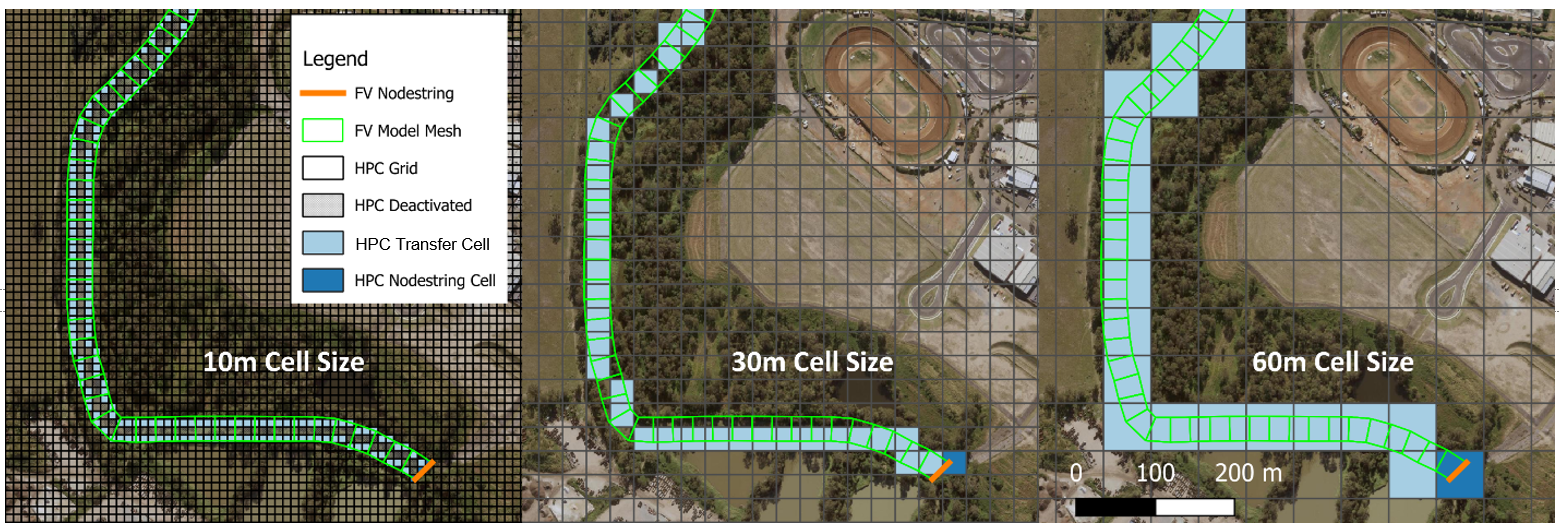
Figure 3.1: Examples of linkages under varying TUFLOW HPC and TUFLOW FV cell resolutions
After all mesh elements and boundary nodestrings are processed, any cells entirely within the TUFLOW FV mesh are deactivated from TUFLOW HPC computations - these locations within the overall model domain are simulated by TUFLOW FV.
The locations of the TUFLOW HPC transfer cells automatically geolocated by TUFLOW CATCH are reported in the TUFLOW HPC ‘hpc_transfer’ check file for review. The corresponding TUFLOW FV boundary condition locations are also reported in the TUFLOW FV ‘bc_check_P’ check files. An example of both is presented in Figure 3.2, with TUFLOW HPC and TUFLOW FV check file outputs on the left (brown squares) and right (red dots), respectively.

Figure 3.2: HPC transfer cell (left) and TUFLOW FV boundary cell (right) check file examples
The above geolocation process does not exclude or prevent the TUFLOW FV user from manually specifying additional boundaries to a TUFLOW FV model. For example, tidal or wastewater discharge (or other) boundaries can be specified by the user within the TUFLOW CATCH control file as per a normal TUFLOW FV model set up by specifying ‘bc’ blocks as required. TUFLOW CATCH will collect these manual (user defined) boundaries and all automatically geolocated boundaries and apply them to the execution of TUFLOW FV under TUFLOW CATCH.
An example of how this geolocation method supports transfer of water, concentrations and momentum is provided in Figure 3.3. The animation presents a catchment derived TUFLOW HPC flow originating from left of screen (and from the fixed grid domain) being transferred automatically into the (flexible mesh) TUFLOW FV domain, and then advected downstream to the right. Constituent concentrations vary from low (blue) to red (high).

Figure 3.3: Example of transferral of an inflow (from left to right) from TUFLOW HPC to TUFLOW FV. Omitted in pdf version