C.9 Other outputs
TUFLOW CATCH produces a small suite of supporting outputs that are simple text files. These are listed below. If the TUFLOW CATCH BC output folder is set to
Catch BC Output Folder
then all files below are written to the
C.9.1 Mass balance
A series of three mass balance files are written as follows (assuming a *.tcc file name of Model_001.tcc).
C.9.1.1 Surface water mass balance
One file per simulation is produced as follows:
- Content:
- Timeseries of spatially summed cumulative surface water flow and associated pollutant masses leaving the TUFLOW HPC model (either to a polygon (Pollutant Export TUFLOW CATCH configuration) or TUFLOW FV model domain (Hydrology and Integrated TUFLOW CATCH configurations))
- Name:
- Model_001_catchment_hydraulic_mass_balance_surface.csv
- Units:
- Uses
- Can be directly imported into common plotting packages to show total surface cumulative flow and pollutant mass export at the outlet of the TUFLOW HPC model domain (or, equally, entry to the TUFLOW FV domain if used)
- Provides an accessible means of high level scenario comparisons, for example where cumulative surface catchment flows and pollutants loads are to be compared between different catchment land use options, management interventions or rainfall sequences
C.9.1.2 Groundwater mass balance
One file per simulation is produced as follows:
- Content:
- Timeseries of spatially summed cumulative groundwater flow and associated pollutant masses leaving the TUFLOW HPC model (either to a polygon (Pollutant Export TUFLOW CATCH configuration) or TUFLOW FV model domain (Hydrology and Integrated TUFLOW CATCH configurations))
- Name:
- Model_001_catchment_hydraulic_mass_balance_groundwater.csv
- Units:
- Uses
- Can be directly imported into common plotting packages to show total groundwater cumulative flow and pollutant mass export at the outlet of the TUFLOW HPC model domain (or, equally, entry to the TUFLOW FV domain if used)
- Provides an accessible means of high level scenario comparisons, for example where cumulative groundwater catchment flows and pollutants loads are to be compared between different catchment land use options, management interventions or rainfall sequences
C.9.1.3 Total mass balance
One file per simulation is produced as follows. Its content is the summation of the data reported in the respective surface and groundwater mass balance outputs described in Sections C.9.1.1 and C.9.1.2:
- Content:
- Timeseries of spatially summed cumulative surface and groundwater flow and associated pollutant masses combined leaving the TUFLOW HPC model (either to a polygon (Pollutant Export TUFLOW CATCH configuration) or TUFLOW FV model domain (Hydrology and Integrated TUFLOW CATCH configurations))
- Name:
- Model_001_catchment_hydraulic_mass_balance.csv
- Units:
- Uses
- Can be directly imported into common plotting packages to show cumulative total flow and pollutant mass export at the outlet of the TUFLOW HPC model domain (or, equally, entry to the TUFLOW FV domain if used)
- Provides an accessible means of high level scenario comparisons, for example where cumulative total catchment flows and pollutants loads are to be compared between different catchment land use options, management interventions or rainfall sequences
C.9.2 Receiving polygon
If TUFLOW CATCH has been executed in the Pollutant Export configuration, then a timeseries output file is produced that reports incoming flow and concentrations to that user defined polygon. This is broadly a concentration based equivalent to the output described in Section C.9.1.3, with some extra fields reported.
Assuming a *.tcc file name of Model_001.tcc has been executed, the file is as follows:
- Content:
- Timeseries of spatially summed instantaneous surface and groundwater flow and associated pollutant concentrations combined leaving the TUFLOW HPC model to a polygon (Pollutant Export TUFLOW CATCH configuration)
- Name:
- Model_001_catchment_hydraulic_receiving.csv
- Units:
- Uses
- Can be directly imported into common plotting packages to show instantaneous total flow and pollutant concentrations at the outlet of the TUFLOW HPC model domain
- Provides an accessible means of high level scenario comparisons, for example where total catchment flows and pollutants concentrations are to be compared between different catchment land use options, management interventions or rainfall sequences
C.9.3 TUFLOW FV boundaries
A series of TUFLOW FV boundary related files are written as follows.
C.9.3.1 BC blocks
A single file that contains all required TUFLOW FV nodestring (Q) and cell (QC) inflow boundary BC blocks is written by TUFLOW CATCH. This file is called automatically by TUFLOW FV under TUFLOW CATCH when required. It is at the heart of the automated linking offered by TUFLOW CATCH. Users should not edit this file in any way.
- Content:
- TUFLOW FV BC blocks that direct TUFLOW FV to boundary condition data files prepared by TUFLOW HPC under TUFLOW CATCH. Only produced in the Hydrology and Integrated TUFLOW CATCH configurations. Two example blocks are shown below
!—————————————————————————————–
! Nodestring boundaries
BC == Q, NW_Inflow, NW_Inflow.csv
Sub-Type == 2
BC Header == Time,Flow,Salinity,Temperature,SED_FINES
End BC
!—————————————————————————————–
! Lateral boundaries
BC == QC, 1178572.028, 4996161.397, cell1.csv
BC Header == Time,Flow,Salinity,Temperature,SED_FINES
End BC
- TUFLOW FV BC blocks that direct TUFLOW FV to boundary condition data files prepared by TUFLOW HPC under TUFLOW CATCH. Only produced in the Hydrology and Integrated TUFLOW CATCH configurations. Two example blocks are shown below
- Name:
- Model_001_catchment_hydraulic.fvcatchbc
- Units:
- NA
- Uses
- Used internally by TUFLOW CATCH to link TUFLOW HPC and TUFLOW FV simulations. Users should not edit this file in any way
This file calls underlying nodestring and/or lateral boundary condition data files produced by TUFLOW HPC, and these are described below.
C.9.3.2 Nodestring boundary data
If TUFLOW CATCH has been executed in the Hydrology or Integrated configuration and TUFLOW FV nodestrings have been specified as catchment inflows via
Catchment BC Nodestring
then individual data files are produced for each nodestring boundary:
- Content:
- Timeseries of flow and associated pollutant concentrations crossing the nodestring
- Name:
- “<GIS name>.csv”, e.g. “SW_Inflow.csv”, where “SW_Inflow” is the user defined name given to the nodestring in GIS
- Units:
- Uses
- Called by Model_001_catchment_hydraulic.fvcatchbc to link TUFLOW HPC and TUFLOW FV under TUFLOW CATCH. Users should not edit this file in any way, including opening and saving it in Excel, which can cause the time format to change and become unreadable.
C.9.3.3 Lateral boundary data
If TUFLOW CATCH has been executed in the Hydrology or Integrated configuration then individual lateral data files are produced for each transfer cell boundary:
- Content:
- Timeseries of flow and associated pollutant concentrations entering a cell
- Name:
- “cell_<TUFLOW mesh cell ID>.csv”, e.g. “cell37.csv”, where 37 is the 2D cell ID in the TUFLOW FV mesh
- Units:
- Uses
- Called by Model_001_catchment_hydraulic.fvcatchbc to link TUFLOW HPC and TUFLOW FV under TUFLOW CATCH. Users should not edit this file in any way, including opening and saving it in Excel, which can cause the time format to change and become unreadable.
C.9.3.4 Intervention summary
If TUFLOW CATCH has been executed in the Pollutant Export or Integrated configuration and with interventions included, then a csv file is produced:
- Content:
- Final cumulative: flows, masses entering and masses removed for all intervention devices and pollutants
- Name:
- “Model_001_catchment_hydraulic_intervention_summary.csv”, in the user specified results folder (assuming “Model_001” is the simulation name)
- Columns:
- Headers
- “QI” cumulative flow
- “cum <pollutant_1_name>” cumulative mass entering device
- “cum <pollutant_2_name>” cumulative mass entering device
- “cum <pollutant_…_name>” cumulative mass entering device
- “cum <pollutant_X_name>” cumulative mass entering device
- “rem <pollutant_1_name>” cumulative mass removed by device
- “rem <pollutant_2_name>” cumulative mass removed by device
- “rem <pollutant_…_name>” cumulative mass removed by device
- “rem <pollutant_X_name>” cumulative mass removed by device
- <device_1_name>
- <device_2_name>
- <device_…_name>
- <device_X_name>
- Headers
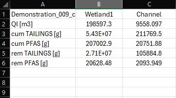
Figure C.1: Example intervention summary output
- Units:
- Uses
- Interrogating pollutant masses removed by intervention devices and therefore the predicted device efficiency, per pollutant. Can also be used in mass balance calculations. When a table is used for specifying removal efficiency then the quotient of removed to entering cumulative masses provides a mean removal rate. It can be verified that this quotient equals the user specified \(R_j\) if
Eqn == Constant is deployed
- Interrogating pollutant masses removed by intervention devices and therefore the predicted device efficiency, per pollutant. Can also be used in mass balance calculations. When a table is used for specifying removal efficiency then the quotient of removed to entering cumulative masses provides a mean removal rate. It can be verified that this quotient equals the user specified \(R_j\) if
