Section 1 Simulation Management
1.1 Overview
Modelling studies often require the simulation of different events or time periods. For example:
- A coastal study may need to consider different seasons, climate change scenarios, multiple tidal periods or the duration of separate dredging campaigns
- A storm tide study may consider different potential combinations of tropical cyclone tracks and tides
- A flood study may have to consider the 0.2, 0.5, 1.0, 2.0, 5.0, 10.0, 20.0 and 50.0% Annual Exceedance Probability (AEP) events and extreme floods
- A water quality study may require investigation of multiple scenarios to assess the impact of proposed changes or the efficacy of management intervention
To assist with associated simulation management and quality control, TUFLOW FV now includes three features as follows, which can be used in combination.
- Model Events
- Event management allows running multiple event combinations (e.g. magnitude, duration, temporal patterns, climate change) using a single set of control files rather than creating a new set of control files for every simulation
- Model Scenarios
- Model Scenarios provide the framework to allow the simulation of different model configurational options (e.g. proposed bathymetric changes) from a single .fvc control file, rather than needing to create separate control files for each scenario
- Model Variables
- Used to assign a user-specified value (that typically appears in multiple locations in a set a control files) to a string variable
Details are provided on how to construct and use events, scenarios and variables in the following sections, after an explanation of the general nomenclature used to do so.
1.2 Nomenclature
A method of text substitution is required in order to use a single *.fvc control file to support re-execution of numerous events and/or scenarios. TUFLOW FV achieves this by using the tilde ‘~’ symbol to surround substitutable event and scenario names in *.fvc filenames. That is, the name given to a *.fvc control file includes tilde pairs for as many scenarios and events are required to be simulated in combination. This same single control file is then called repeatedly but with differing scenario and event arguments sent to it, that then perform various functions within the *.fvc as described below. These arguments are substituted where tilde pairs are present in the *.fvc filename.
For example, if a particular model required consideration of two events (perhaps one inflow and one tidal) and one scenario (perhaps bathymetric settings) then the *.fvc will need to accommodate these three substitutable quantities using tilde pairs, and therefore might be named as follows (where ‘eX’ and ‘sX’ are keywords that refer to events and scenarios, respectively, and X is a sequential integer).
Model_~e1~_~e2~_~s1~_001.fvcIf in one instance the user had then set e1 to be ‘Q100’, e2 to be ‘HighTide’ and s1 to be ‘BASECASE’, then the above reusable *.fvc would be interpreted as follows.
Model_Q100_HighTide_BASECASE_001.fvcImportantly, this *.fvc would not be created as such (doing so would defeat the purpose of using wildcards in a single *.fvc) but the results files the simulation write would be named accordingly.
Model_Q100_HighTide_BASECASE_001.nc
Model_Q100_HighTide_BASECASE_001.csv
This means that only one *.fvc is used, but multiple sets of uniquely named output files are created.
In addition to the above tilde substitution for events and scenarios, variables are referred to within *.fvc files using double angled bracket nomenclature. For example, if a user has specified that a variable called DO_HIGH has a value of 6.0, then the variable DO_HIGH can be referenced anywhere subsequently in an *.fvc as <<DO_HIGH>>. An example of setting water quality initial conditions is provided below.
The use of this nomenclature in setting up and executing scenarios and events, and deploying variables, is described following.
1.3 Events
Event management allows running multiple event combinations (e.g. magnitude, duration, temporal patterns, climate change) using a single set of control files rather than creating a new set of control files for every simulation. For example, a flood study requires simulation of the 1%, 2% and 5% Annual Exceedence Probability (AEP). Each AEP needs to be run for the 1hr and 2hr storm duration. The number of .fvc files required with and without event management is shown in Figure 1.1.
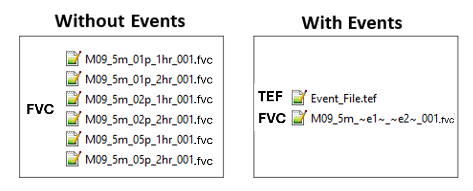
Figure 1.1: Reduction of Control Files using Event Management
1.3.1 TUFLOW Event File
Multiple events are set up through the creation of a TUFLOW Event File (recommended extension .tef) containing .fvc commands that are particular to a specific event.
The .tef file is referenced in the .fvc file using the command
The location of Event File within the .fvc file and the location of the
commands within the .tef file are important. Specifically, the commands
from the .tef file (for the events specified using the –e run option or the
The following is an example TUFLOW Event File call within the .fvc file.
Within the .tef, event-specific commands are contained between
Any TUFLOW FV command can be placed within a define event block, however event blocks are typically used for commands that relate to model boundary conditions, and simulation period, such as start and end times. Global .fvc commands can also be used in the .tef by placing commands outside the Define Event blocks (normally at the top).
The new command
An example .tef is provided as follows, noting that it conforms to the same general nomenclature as described in Section 1.2 with pairs of tildes surrounding text that is to be substituted. Since these substitutable text strings are not part of a *.fvc control file name, they can be user defined and are not keywords (e.g. ‘aep’ is user defined as below, but e1 is a keyword).
The
- In the Define Event block the
Timestep Limits are selected as a function of the event severity. Timesteps are modified to allow for events with larger water depths and velocities. BC Event Source assigns dynamic text replacement variables for rainfall intensity and storm duration.
Using the above event block example as a guide, dynamic text replacement
using
- Replacement of text in directory and file paths to the right of the == is supported. For example:
becomes:
- Replacement of command input parameters to the right of the == is supported. For example:
becomes:
- Replacement is not allowed in TUFLOW FV command syntax to the left of the ==. For example:
Will result in an error due to the ~aep~ to the left of the ==.
- BC Event Source text replacement is currently limited to .fvc and include file commands. It is not currently available for commands within Sediment Transport (.fvsed), Water Quality (.fvwq) and Particle Tracking (.fvptm) Control Files.
1.3.2 Running Events
Two options are available to run multiple events from the same .fvc file:
- Using a batch file (.bat): Specifying –e or –eX options (where X is a number from 1 to 9) to run the multiple events using the same .fvc file – refer to the Event Examples. This is the recommended approach.
- Using the
Model Events command: Change the events manually before each simulation within the .fvc file. Note that if using the –e option, a .bat file –e events will override any events defined using Model Events within the .fvc. The Model Events command is typically used to set the default event(s).
To automatically insert the name of the event(s) into the output filenames so as to make the output names unique, place “~e~” or “~e<X>~” where <X> is a number from 1 to 9 into the .fvc file name as shown in the following example.
MODEL_~e1~_001.fvc

Can be configured to run any number of e1 event names:

- e1=0100F:  MODEL_0100F_001.fvc
- e1=0200F:  MODEL_0200F_001.fvc
- e1=0500F:  MODEL_0500F_001.fvc
- e1=1000F:  MODEL_1000F_001.fvc
Multiple events can be simulated from the one .fvc file using a batch file. The example below uses three events to vary the event rainfall intensity, duration and temporal pattern.
set EXE=C:\Program Files\TUFLOWFV\TUFLOWFV.exe
set OMP_NUM_THREADS=4
%EXE%   –e1         10pct   –e2         01h     –e3         T01         Nile_~e1~_~e2~_~e3~_001.fvc
%EXE%   –e1         10pct   –e2         01h     –e3         T02         Nile_~e1~_~e2~_~e3~_001.fvc
%EXE%   –e1         10pct   –e2         02h     –e3         T01         Nile_~e1~_~e2~_~e3~_001.fvc
%EXE%   –e1         10pct   –e2         02h     –e3         T02         Nile_~e1~_~e2~_~e3~_001.fvc
%EXE%   –e1         05pct   –e2         01h     –e3         T01         Nile_~e1~_~e2~_~e3~_001.fvc
%EXE%   –e1         05pct   –e2         01h     –e3         T02         Nile_~e1~_~e2~_~e3~_001.fvc
%EXE%   –e1         05pct   –e2         02h     –e3         T01         Nile_~e1~_~e2~_~e3~_001.fvc
%EXE%   –e1         05pct   –e2         02h     –e3         T02         Nile_~e1~_~e2~_~e3~_001.fvc
%EXE%   –e1         02pct   –e2         01h     –e3         T01         Nile_~e1~_~e2~_~e3~_001.fvc
%EXE%   –e1         02pct   –e2         01h     –e3         T02         Nile_~e1~_~e2~_~e3~_001.fvc
%EXE%   –e1         02pct   –e2         02h     –e3         T01         Nile_~e1~_~e2~_~e3~_001.fvc
%EXE%   –e1         02pct   –e2         02h     –e3         T02         Nile_~e1~_~e2~_~e3~_001.fvc
%EXE%   –e1         01pct   –e2         01h     –e3         T01         Nile_~e1~_~e2~_~e3~_001.fvc
%EXE%   –e1         01pct   –e2         01h     –e3         T02         Nile_~e1~_~e2~_~e3~_001.fvc
%EXE%   –e1         01pct   –e2         02h     –e3         T01         Nile_~e1~_~e2~_~e3~_001.fvc
%EXE%   –e1         01pct   –e2         02h     –e3         T02         Nile_~e1~_~e2~_~e3~_001.fvc
When many events are to be executed, it can be convenient to do so through a series of loops in a batch file, rather than listing multiple rows of (relatively repetitive) commands as above. Native batch file syntax can be used to do so (in Windows), by defining arrays and then looping through these arrays accordingly. For example, the above 16 calls to TUFLOW FV can be written more succinctly (and robustly) as follows.
set EXE=C:\Program Files\TUFLOWFV\TUFLOWFV.exe
set OMP_NUM_THREADS=4

REM Set arrays e1, e2 and e3
set ev1=10pct 05pct 02pct 01pct
set ev2=01h 02h
set ev3=T01 T02

REM Loop through arrays
for %%a in (%ev1%) do (
  for %%b in (%ev2%) do (
    for %%c in (%ev3%) do (
      %EXE% -e1 %%a -e2 %%b -e3 %%c Nile_~e1~_~e2~_~e3~_001.fvc
    )
  )
)
For further examples on running events from batch files, including advanced batch looping refer to the TUFLOW FV Wiki.
1.3.3 Event Examples
Three examples are presented below.
- Examples 1 and 2 are an estuary model use case that runs a series of simulation years 2016-2018. Example 1 uses one type of event to select the year to run. Example 2 adds a second event to select climate change allowances for inflow and downstream water levels.
- Example 3 is a catchment model that uses three events to run combinations of rainfall event intensities, durations and temporal patterns.
In the examples, note how the start and end time, initial conditions, and output dir commands are used within the event blocks to vary the model configuration as a function of the event simulated.
Events Example 1
Within each BC Block:
Include “~e1~” in the .fvc file name, for example
“Example_Estuary_~e1~_001.fvc”, and add the following line:
The “Estuary Events.tef” file contains the following.
! Global Default Settings
! Simulation Year Event Definitions
Multiple events can be simulated from the one .fvc file using a batch file. For more information on running batch files refer to the TUFLOW FV Wiki.
set EXE=C:\Program Files\TUFLOWFV\TUFLOWFV.exe
set OMP_NUM_THREADS=4
%EXE%   –e1         2016        Example_Estuary_~e1~_001.fvc
%EXE%   –e1         2017        Example_Estuary_~e1~_001.fvc
%EXE%   –e1         2018        Example_Estuary_~e1~_001.fvc
Events Example 2
Within each BC Block:
Include “~e1~” and “~e2~” in the .fvc file name, for example “Example_Estuary_~e1~_~e2~_001.fvc”, and add the line: Event File == Estuary_Events.tef
The “Estuary Events.tef” file contains the following:
! Global Default Settings
! Simulation Year Event Definitions
! Climate Change Definitions
Multiple events can be simulated from the one .fvc file using a batch file. For more information on running batch files refer to the TUFLOW FV Wiki.
set EXE=C:\Program Files\TUFLOWFV\TUFLOWFV.exe
set OMP_NUM_THREADS=4

%EXE%   –e1         2016    –e2         CC_EXST         Example_Estuary_~e1~_~e2~_001.fvc
%EXE%   –e1         2016    –e2         CC_2050         Example_Estuary_~e1~_~e2~_001.fvc
%EXE%   –e1         2016    –e2         CC_2100         Example_Estuary_~e1~_~e2~_001.fvc
%EXE%   –e1         2016    –e2         CC_2150         Example_Estuary_~e1~_~e2~_001.fvc
%EXE%   –e1         2017    –e2         CC_EXST         Example_Estuary_~e1~_~e2~_001.fvc
%EXE%   –e1         2017    –e2         CC_2050         Example_Estuary_~e1~_~e2~_001.fvc
%EXE%   –e1         2017    –e2         CC_2100         Example_Estuary_~e1~_~e2~_001.fvc
%EXE%   –e1         2017    –e2         CC_2150         Example_Estuary_~e1~_~e2~_001.fvc
%EXE%   –e1         2018    –e2         CC_EXST         Example_Estuary_~e1~_~e2~_001.fvc
%EXE%   –e1         2018    –e2         CC_2050         Example_Estuary_~e1~_~e2~_001.fvc
%EXE%   –e1         2018    –e2         CC_2100         Example_Estuary_~e1~_~e2~_001.fvc
%EXE%   –e1         2018    –e2         CC_2150         Example_Estuary_~e1~_~e2~_001.fvc
Events Example 3
The following example shows the setup for a floodplain model with multiple different design rainfall intensities, rainfall durations, and temporal patterns.
Within each BC Block:
Include “~e1~”, “~e2~”, and “~e3~” in the .fvc file name, for
example “Nile_~e1~_~e2~_~e3~_001.fvc”, and add the line:
The “Nile Events.tef” file contains the event block logic provided below.
! Global Default Settings
! Annual Exceedance Probability Definitions
! Storm duration definitions
! Temporal patterns definitions
1.3.4 Additional Functionality
1.3.4.1 Event Logic Blocks
Whilst an
The Pause command causes TUFLOW FV to stop whenever it is encountered, which in the above case would be if no event had been specified called any of Q1, Q10, Q50 or Q100.
‘Or’ logic can also be used in blocks such as the above by deploying the ‘|’ character. Noting that the Q50 and Q100
1.3.4.2 Events as Variables
Events are also automatically defined as variables and can be assigned accordingly within *.fvc control files. For example, if multiple events (e1) were set up and executed but a separate folder was desired for each events’s suite of outputs, then the following syntax in the *.fvc would accomplish this outcome.
If e1 was set be Q2 then the above would be interpreted as
Similar approaches can be applied to other TUFLOW FV *.fvc commands.
1.4 Scenarios
When completing project or research work, it is common to require the comparison of the ‘existing’ or ‘base case’ conditions with a future ‘design’, or series of ‘design options’. This may include for example:
- Earthworks or changes in landuse for a proposed coastal or floodplain development
- New capital works for a new port, dredge channel, or a series of new channel designs
- Changes to dam operations
- Different bridge or structure upgrade options
Model Scenarios provide the framework to allow the simulation of different design options from a single .fvc control file, rather than needing to create separate control files for each scenario.
The
1.4.1 Running Scenarios
The approach to running scenarios is analogous to Model Events, with the exception that a ‘Scenario File’ similar to the ‘Event File .tef’ is not required.
Two options are available to run scenarios from the same .fvc file:
- Using a batch file (.bat): Specifying –s or –sX options (where X is a number from 1 to 9) to run single, or mutliple scenarios using the same .fvc file – refer to the Scenario Examples. This is the recommended approach.
- Using the
Model Scenarios command: Change the scenarios manually before each simulation within the .fvc file. Note that if using the –s option, a .bat file –s calls will override any scenarios defined using Model Scenarios which is defined within the .fvc. The Model Scenarios command is typically used to set the default scenario(s).
To automatically insert the name of the scenario(s) into the output filenames so as to make the output names unique, place “~s~” or “~s<X>~” where <X> is a number from 1 to 9 into the .fvc. For example a study on the Mary River with fvc name:
MR_~s1~_~s2~_001.fvcCan be configured to run any number of s1 and s2 scenario. For example:
set EXE=C:\Program Files\TUFLOWFV\TUFLOWFV.exe
set OMP_NUM_THREADS=4

%EXE%   –s1         EXG   –s2         BASE        MR_~s1~_~s2~_001.fvc
%EXE%   –s1         DEV   –s2         OPT1        MR_~s1~_~s2~_001.fvc
%EXE%   –s1         DEV   –s2         OPT2        MR_~s1~_~s2~_001.fvc
%EXE%   –s1         DEV   –s2         OPT3        MR_~s1~_~s2~_001.fvc
becomes:
s1=EXG and s2=BASE:   MR_EXG_BASE_001.fvc
s1=DEV and s2=OPT1:   MR_DEV_OPT1_001.fvc
s1=DEV and s2=OPT2:   MR_DEV_OPT2_001.fvc
s1=DEV and s2=OPT3:   MR_DEV_OPT3_001.fvc
Note that the character length for s1 (3) and s2 (4) is consistent between each run. This is optional.
For further examples on running scenarios from batch files, including advanced batch looping refer to the TUFLOW FV Wiki.
1.4.2 Scenario Examples
Scenarios Example 1
In a .fvc file:
TUFLOW FV will carry out the following steps:
- Set all material values over the entire 2D domain to a value of 1.
- Process the 2d_mat_existing.shp layer to assign material values from a layer of land-use polygons representing the existing situation.
- One of the following will then occur:
If “-s1 opA” is specified as a run option in a batch file, or
Model Scenarios == opA is specified in the .fvc file, then the 2d_mat_opA.shp layer is processed to modify the material values where Option A has changed the landuse. If “~s1~” occurs within the .fvc filename, it is replaced by “opA” in the output filenames, otherwise “opA” is appended to the .filename for the output filenames.If opA was not specified as a scenario, this layer would be ignored. For example, as would be required if modelling the existing scenario.
Example 1 can be extended to include an Option B, where Option B is a modified version of Option A as shown in Example 2a below.
Scenarios Example 2a
In the above example, either “–s opB” or “–s1 opA –s2 opB” can be used for the run options when modelling the Option B scenario.
Scenarios Example 2b
Alternatively, the following would give the same result.
In the above, either “–s opB” or “Model Scenarios == opB” would be used when modelling Option B. If the Existing, Option A and Option B scenarios all had their own layer of materials for the whole model the commands could be laid out as shown in Example 2c noting the use of the Else option which forces the use of the layer 2d_mat_existing.shp if opA or opB is not specified.
Scenarios Example 2c
Or, a more explicit approach is shown below.
Scenarios Example 3
The If Scenario command can be nested up to 10 levels. The extract below is from an .fvc file of a complex model that calls various model sub-domains at different floodplain mesh resolutions (20m and 60m). The logic as to which other sub-models/boundaries the CAS sub-model needs is built into include files using nested If Scenarios.
The Pause command causes TUFLOW FV to stop whenever it encounters it. In the example above, the Pause command is used to pause the simulation and display the message shown as a cross-check that an appropriate cell size scenario has been specified.
Any scenarios are automatically set as variables, so have uses parallel to those described for Events above.
1.5 Variables
The
Note: Set variable commands can only be specified in the .fvc or within an include file referenced from the .fvc. They are not yet available within sediment, particle or water quality control files.
The example below is a floodplain model where two different mesh resolutions are being tested. To manage the size of result output, the variable “NC_OUTPUT_INTERVAL” is used to set the map output interval.
In the .fvc file we have the following syntax.
! MODEL VARIABLES
The variable NC_OUTPUT_INTERVAL is dynamically replaced at runtime to adjust the NetCDF output interval.
The Set Variable functionality available in TUFLOW FV 2025.0.0 can be used in combination with the assignment batch/shell script environment variables (Introduced in TUFLOW FV 2023.1). For example:
REM Example batch file that uses the environment variable IWL to set initial water level
set EXE=C:\Program Files\TUFLOWFV\TUFLOWFV.exe
set OMP_NUM_THREADS=4
set IWL=2.0

%EXE% Env_Var_Example.fvc
Within the .fvc file the environment variable value is returned via the $ syntax. For example:
achieves the same outcome as the variable syntax shown below.
1.6 Simulation Management Example Models
TUFLOW FV’s Example Model dataset has been updated with ten new examples models to allow you to test and interact with the new event, scenario and variable functionality. The models can be run without a TUFLOW FV license.
