This is an interim changelog that accompanies the TUFLOW FV 2026.0.0 beta release. The information contained within this interim version may vary from the final version.
Changelog for TUFLOW FV 2026.0.0
Release date: 20 Feb 2026
Build: 2026.0.0-beta.1
General Notes
The 2026 TUFLOW FV release is a major release that contains a number of enhancements. These include TUFLOW FV Build Process Updates and Enhancement of Destratification Unit Structure Type. A new feature called Auto Terminate is included which automatically stops a simulation when a user defined water level threshold is reached at a specified location.
The Get Tools package within the TUFLOW FV Python Toolbox environment has been updated to improve workflows and increase compatibility with global and regional atmospheric, tidal and ocean models.
Backwards Compatibility
The 2026.0.0 release may cause changes in results if upgrading from previous releases. This is due to the TUFLOW FV Build Process Updates. Notwithstanding this, testing to date of the 2026.0.0 release has shown negligible changes to the results when upgrading from previous releases. However, it is recommended that when switching between new releases with an established model, that test runs are carried out and comparisons made between the old and new releases.
New Features and Enhancements
TUFLOW FV Build Process Updates
The TUFLOW FV 2026.0.0 release has been built using the current Intel oneAPI Fortran compiler (ifx), replacing the legacy ifort compiler to maintain ongoing support and compatibility with modern systems. This is a build system update only and does not change model configuration or workflows. Testing confirms results are consistent with previous releases to within normal numerical precision, therefore changes in model outputs are not expected.
The TUFLOW FV GPU module build process has been updated from CUDA 11.8 to CUDA 12.9. This maintains compatibility with current NVIDIA hardware and continues support for GPUs supported in the TUFLOW FV 2025 releases. GPU users may need to upgrade NVIDIA drivers to meet the minimum driver requirements for CUDA 12.9.
The Windows build has been tested on Windows 10 and Windows 11. The Linux build has been tested on Ubuntu 22.04 and Rocky Linux 9, with both .deb and .rpm installation packages provided. The .rpm package is built against modern RHEL 9 compatible distributions and will not run on legacy variants such as RHEL 7 or CentOS 7. Similarly, the .deb package is targeting modern glibc 2.35+ environments and is not compatible with legacy distributions such as Ubuntu 18.04 or Debian 10.
Enhancement of Destratification Unit Structure Type
The destratification unit structure type simulates the entrainment and detrainment of flow associated with bubble plume diffusers.
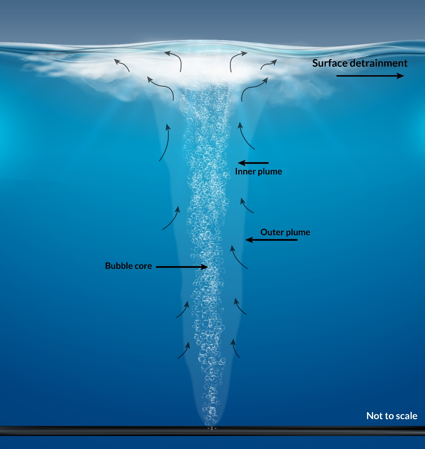
In general, there are four options to specify the flow rate assigned to a destratification unit:
- Constant airflow specified at the diffuser head [m3/s/plume]. This assumes the user has manually pre-corrected the airflow to allow for increased pressure at depth.
- Airflow timeseries specified at the diffuser head [m3/s/plume]. This assumes the user has manually pre-corrected the airflow to allow for increased pressure at depth.
- Constant airflow specified at atmospheric pressure. TUFLOW FV automatically corrects for the airflow rate at the diffuser head [m3/s/plume].
- Airflow timeseries specified at atmospheric pressure. TUFLOW FV automatically corrects for the airflow rate at the diffuser head [m3/s/plume].
The TUFLOW FV bubbler calculations outputs are supported by the structflux output block. Refer to the TUFLOW FV 2025.2.4 Release Notes for details.
Model Setup
To define the bubbler location, only one cell should be selected per structure. It is recommended that the location is set via TUFLOW FV’s
This layer (2d_zn):
- Uses TUFLOW FV empty template
2d_znregion layers - Should include only one 2D cell per zone polygon. Cells are selected if a mesh cell centroid is within a polygon extent, so therefore care is required when changing meshes, or when digitising so that only one cell is selected by each polygon.
- Has a single attribute
Namethat requires a unique string name which is later referenced in the structure block for that cell, including in outputs such asstructflux
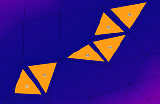
The image below presents an example from a model that will include six destratification unit structure blocks. The layer includes six polygons, each selecting one cell. The polygons are named B1, B2, B3, B4, B5 and B6.
Structure Block Setup
Each bubbler polygon requires a separate structure block within the TUFLOW FV control file (.fvc). This allows for full flexibility when specifying air flow rates and/or pipe elevations at different lineal positions along the device.
One structure block per cell is needed. For example, to assign bubble plumes to each of the six 2D cells B1 to B6 in the image above, six separate structure blocks are required in the TUFLOW FV control file (.fvc).
These structure blocks are instantiated using the
The mandatory commands are:
-
Destratification Unit == <type> , where<type>is either:Bubbler: for airflow rate at the diffuser head, orCompressor: specified at atmospheric pressure and corrected by TUFLOW FV. This correction is dynamic and responds to changing water levels.
-
Properties == <list> , where<list>is set to the following in comma separated order:- Bubbler pipe elevation: an absolute elevation in the model vertical datum [m]
- Flow rate: the airflow rate [m3/s/plume]
- If
Destratification Unit == Bubbler this is the airflow rate at the diffuser head - If
Destratification Unit == Compressor this is the airflow rate at the surface at atmospheric pressure. If aControl block specifying a timeseries is used, this number is ignored and the control timeseries data is applied
- If
- Number of plumes in the structure
- Alpha: set to
0.0833. Do not change - b1: set to
4.7. Do not change - Lr: set to
0.1. Do not change - Gamma: detrainment coefficient. Linear multiplier to set detrainment
The optional command block (if timeseries airflow rates are required):
-
Control == <control_type> . Start of control block. Set<control_type>toTimeseriesto allow varied airflow rate. -
Control Update dt == <time> , where<time>is set to the interval the model checks the input timeseries to update the airflow rate [hrs, not seconds] -
Control Parameter == <control_type> , where<param>is either:Airflow_Bubbler: ifDestratification Unit == Bubbler , orAirflow_Compressor: ifDestratification Unit == Compressor
-
Control File == <file_name> , where<file_name>is set to the timeseries.csvfile. Note:- If
Control Parameter == Airflow_Bubbler , the.csvmust have the headersTime,Airflow_Bubbler - If
Control Parameter == Airflow_Compressor , the.csvmust have the headersTime,Airflow_Compressor
- If
-
End Control . Closes the structure control block.
Examples
-
Constant airflow specified in m3/s/plume at the diffuser head:
Read GIS Zone == ..\model\gis\2d_zn_Bubbler_001_R.shp
Structure == Zone, B1
Destratification Unit == Bubbler
Properties == 47, 0.001, 2, 0.0833, 4.7, 0.1, 0.95
! 47 = Elevation (mRL)
! 0.001 = Air flow rate at diffuser head (m3/s/plume)
! 2 = Number of plumes in the cell
! 0.0833 = Alpha
! 4.7 = b1
! 0.1 = Lr
! 0.95 = Gamma
End Structure -
Airflow timeseries specified in m3/s/plume at the diffuser head:
Read GIS Zone == ..\model\gis\2d_zn_Bubbler_001_R.shp
Structure == Zone, B1
Destratification Unit == Bubbler
Properties == 47, 0.001, 2, 0.0833, 4.7, 0.1, 0.95
! 47 = Elevation (mRL)
! 0.001 = Air flow rate at diffuser head (m3/s/plume), ignored
! 2 = Number of plumes in the cell
! 0.0833 = Alpha
! 4.7 = b1
! 0.1 = Lr
! 0.95 = Gamma
Control == Timeseries
Control Update dt == 0.1 ! hrs
Control Parameter == Airflow_Bubbler
Control File == ../model/csv/Bubbler_AirFlow_PerPlume.csv
! Headers: Time, Airflow_Bubbler (m3/s/plume at depth)
End Control
End Structure -
Constant airflow specified in m3/s/plume at atmospheric pressure:
Read GIS Zone == ..\model\gis\2d_zn_Bubbler_001_R.shp
Structure == Zone, B1
Destratification Unit == Compressor
Properties == 47, 0.003, 2, 0.0833, 4.7, 0.1, 0.95
! 47 = Elevation (mRL)
! 0.003 = Air flow rate at atmospheric pressure (m3/s/plume)
! 2 = Number of plumes in the cell
! 0.0833 = Alpha
! 4.7 = b1
! 0.1 = Lr
! 0.95 = Gamma
End Structure -
Airflow timeseries specified in m3/s/plume at atmospheric pressure:
Read GIS Zone == ..\model\gis\2d_zn_Bubbler_001_R.shp
Structure == Zone, B1
Destratification Unit == Compressor
Properties == 47, 0.002, 2, 0.0833, 4.7, 0.1, 0.95
! 47 = Elevation (mRL)
! 0.002 = Air flow rate at atmospheric pressure (m3/s/plume), ignored
! 2 = Number of plumes in the cell
! 0.0833 = Alpha
! 4.7 = b1
! 0.1 = Lr
! 0.95 = Gamma
Control == Timeseries
Control Update dt == 0.1 ! hrs
Control Parameter == Airflow_Compressor
Control File == ../model/csv/Compressor_AirFlow_PerPlume.csv
! Headers: Time, Airflow_Compressor
(m3/s/plume at atmospheric pressure)
End Control
End Structure
Auto Terminate Feature
The Auto Terminate feature automatically stops a simulation once a specified water level threshold is reached at a user defined monitoring location.
At model startup, TUFLOW FV reads the initial water level at the specified location (IWL) and compares it to the user defined target water level (WL_target). The simulation tracks the model water level at the specified location (MWL) and TUFLOW FV cleanly exits once the target condition is met. The auto termination is based on the following logic:
- If
IWL>WL_target, TUFLOW FV assumes that water levels will follow a decreasing trend during the simulation and will terminate whenMWL≤WL_target. - If the
IWL<WL_target, TUFLOW FV assumes that water levels will follow an increasing trend during the simulation and will terminate whenMWL≥WL_target.
This feature is enabled using the following command:
Auto Terminate == {0} | 1, X_COORDINATE, Y_COORDINATE, WL_target
Where:
{0} | 1: Enables or disables the feature:0: Disables Auto Terminate (Default)1: Enables Auto Terminate
X_COORDINATE: The X coordinate of the monitoring point (map units)Y_COORDINATE: The Y coordinate of the monitoring point (map units)WL_target: The target water level at which the simulation will stop (mRL or ftRL)
The log file reports the 2D cell ID associated with the specified monitoring location and if the coordinates fall outside the model domain, TUFLOW FV will return an error.
Write XMDF Files Using HDF5 Library
TUFLOW FV now writes XMDF outputs by utilising the HDF5 library directly rather than through the intermediary XMDF library. This change allows the use of the most up-to-date HDF5 library. The generated files should be equivalent.
Get Tool Updates
The Get Tools package within the TUFLOW FV Python Toolbox environment has been updated. This tool is designed to help modellers download and format boundary condition data commonly used in TUFLOW FV.
The latest updates and enhancements to Get Tools include:
- Get Tide, Get Atmos and Get Ocean have been merged into a new package
tfv-get-tools. - Get Tide supports the global tide models FES 2014 and FES 2022b from the Finite Element Solution Global Tide model (FES) distributed by AVISO.
- Get Ocean has been expanded to include an additional ocean model from Copernicus Marine.
- Get Atmos has been updated from the BARRA atmospheric model to BARRA2 produced by the Bureau of Meteorology.
Accompanying this new release of Get Tools is a new suite of TUFLOW FV Wiki tutorials demonstrating how to use the latest tfv-get-tools package:
Visit the TUFLOW FV Get Tools Update and Installation Wiki for instructions on how to install or update the latest tfv-get-tools package.